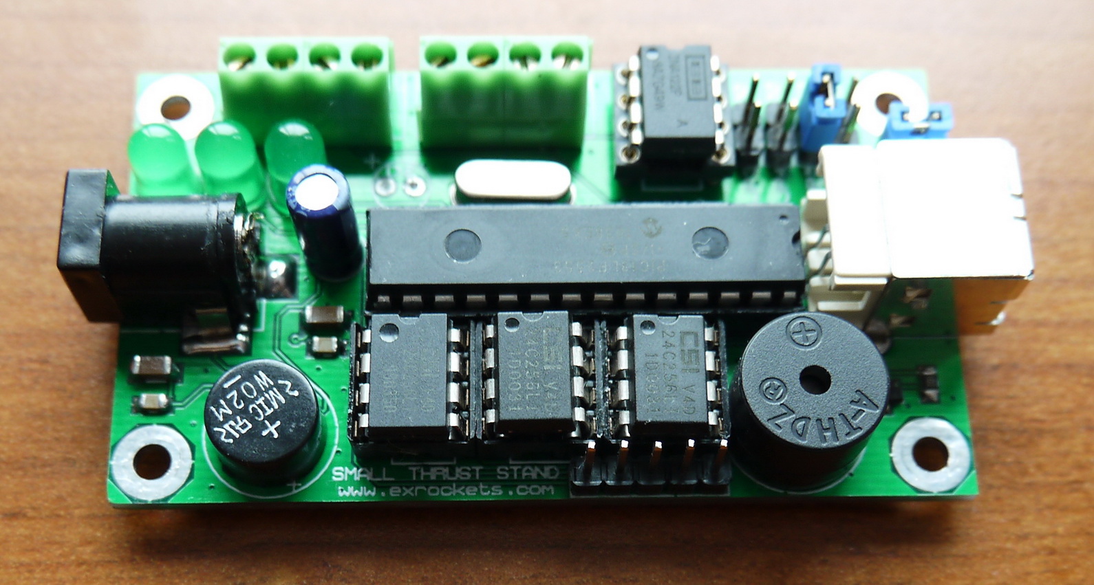
After I made my main DAQ system (ROCKET THRUST STAND DAQ SYSTEM WITH GLCD) I decided to make something smaller, less sophisticated and more energy efficient. So after some thinking about what functionality should I have and how much energy efficient the system should be I came with the following device:
DAQ system Description:
– This DAQ system can be powered from 8.5 volts to 12 volt DC or AC sources, where the polarity of the connectors is not important. If the supply voltage drops below 8.5v the system still will be working but the readings will no longer be correct
*Please note that some rechargeable “9 volt” batteries have actual nominal voltage of less than 8.5 volt
– The total consumption while recording the test is about 50 mA
– It can record up to 3 tests before you will need to erase the memory
– The total test time allowed per bank of memory is approximately 16 seconds
– Can work in autonomous mode where the data is stored in memory or in real-time mode by sending the data directly to the PC
– In stand-alone mode the time stamp is 0.002 seconds
– In real-time mode the time stamp is 0.01 seconds
– Circular buffer that keeps data for 1/4 second before the detected start
– Automatically detects the start
– Low-voltage detection
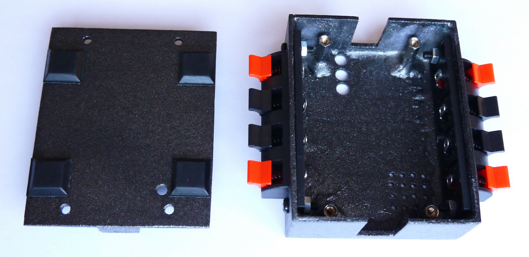
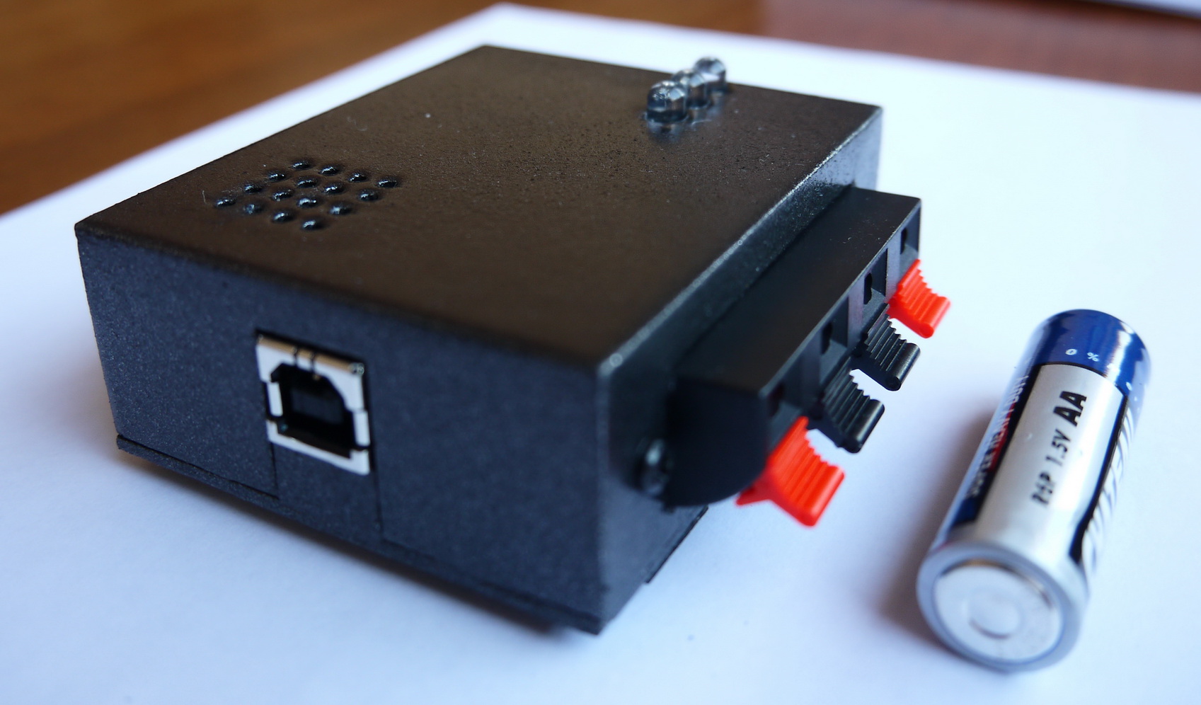
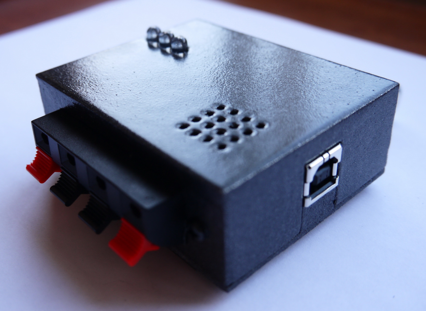
– There are two ports – PORT A and PORT B
– Port A is intended for load cells (this is normally where the thrust stand is connected)
– Port B can be used to connect another source to be digitalized where the input voltage shouldn’t exceed 5 volts (although there is a clamping diode that should prevent damage to the system if this voltage is surpassed)
– JP1 (the one next to the USB port) will enable/disable the buzzer
– JP3 to JP6 will select the system gain – 100, 200, 500 and 1000 times. This is to say that the signal from the load cell will be amplified that many times
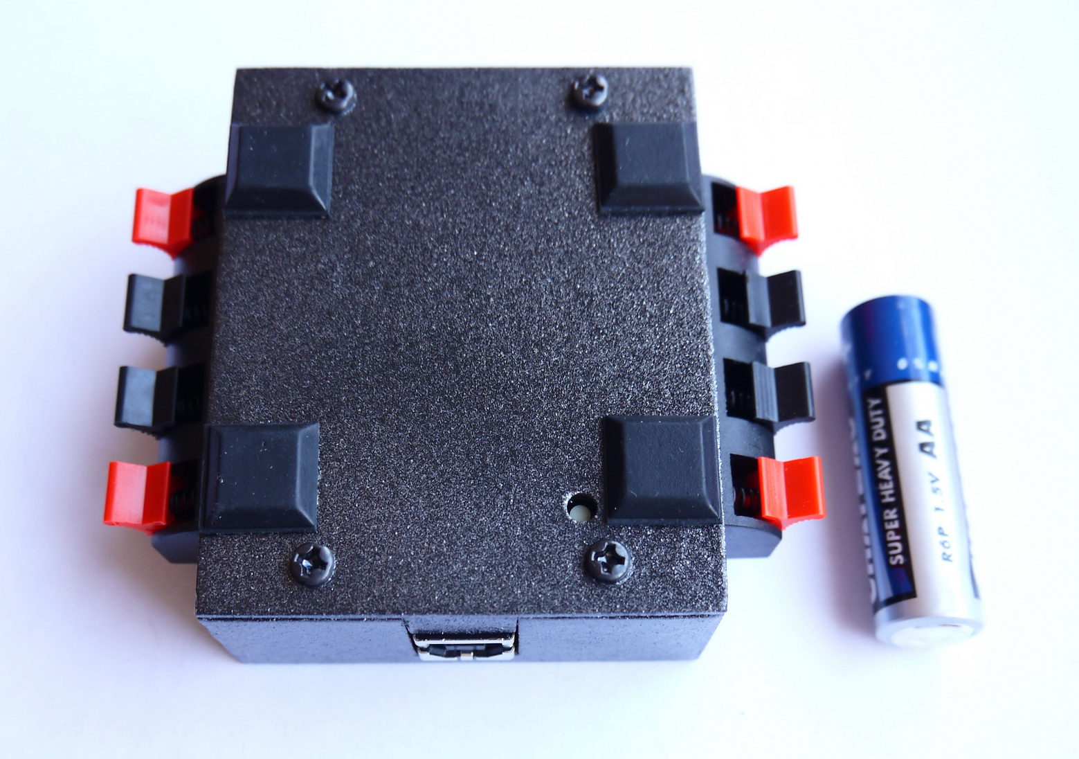
– The small button on the bottom side is intended to provide the possibility to format the device even when it is not connected to a computer. To prevent accidental erasure there is a procedure to follow before the memory can be erased
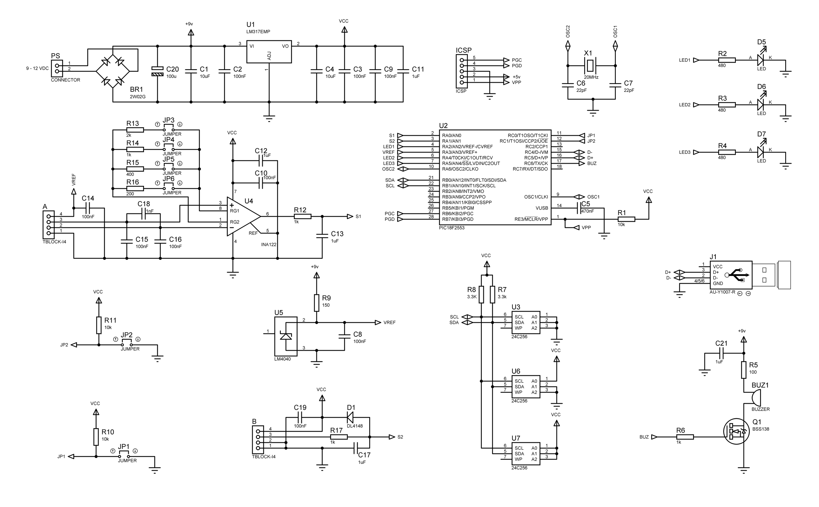
LOW-VOLTAGE DETECTION:
This reference diode is configured to work in the range from 8.5 to 12v with a standard load cell load of more than 300 Ohm. The LDO regulator works down to 6v while keeping 5 volt output. However if the power supply drops below 8.5v the output from the reference diode (under load) will be lower than 5 volts.
The system will compare the voltage output from the 5 volt reference diode and the LDO regulator. If there is a difference of more than 50 mV from both outputs the system will stop and give a continuous audio signal meaning that the battery output is less than 8.5 volts.
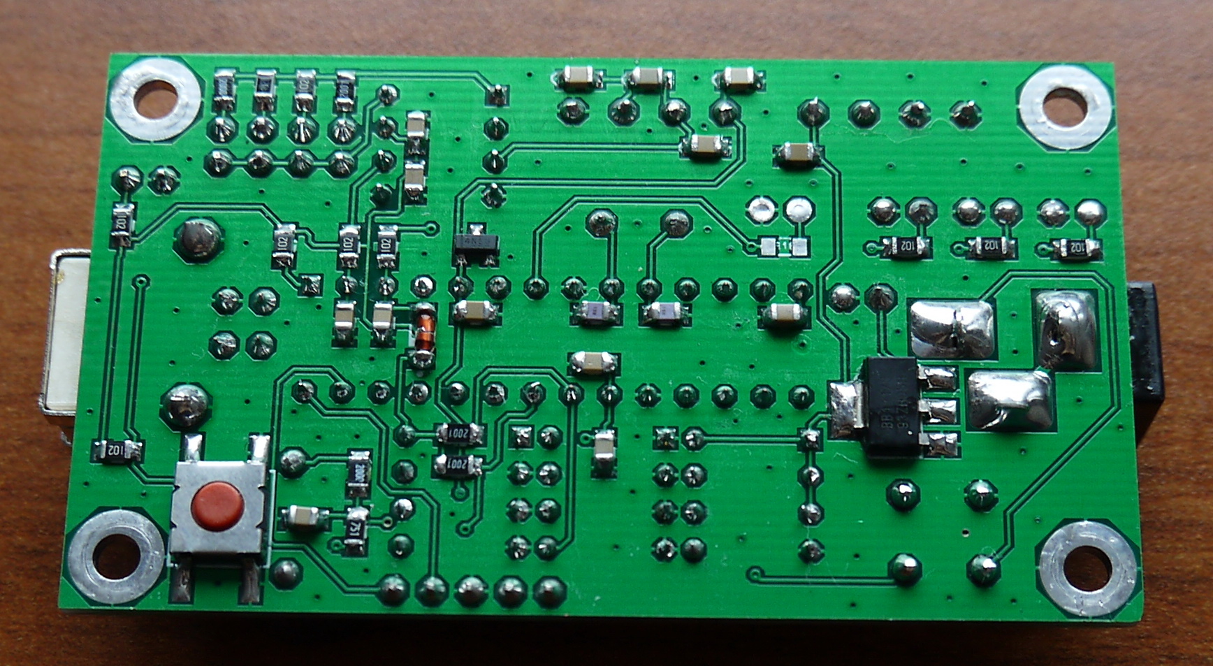
Next step was to make the PCB. Although I used mostly DIP ICs for this DAQ, the PCB has relatively small dimensions – 40mm x 70mm.

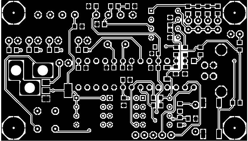
Once I got the PCBs it was time to solder all components
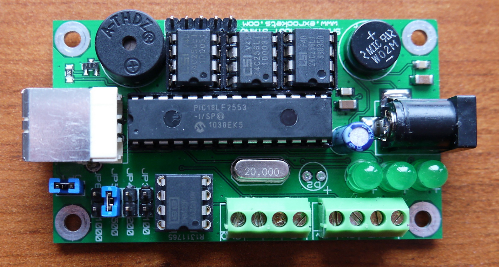
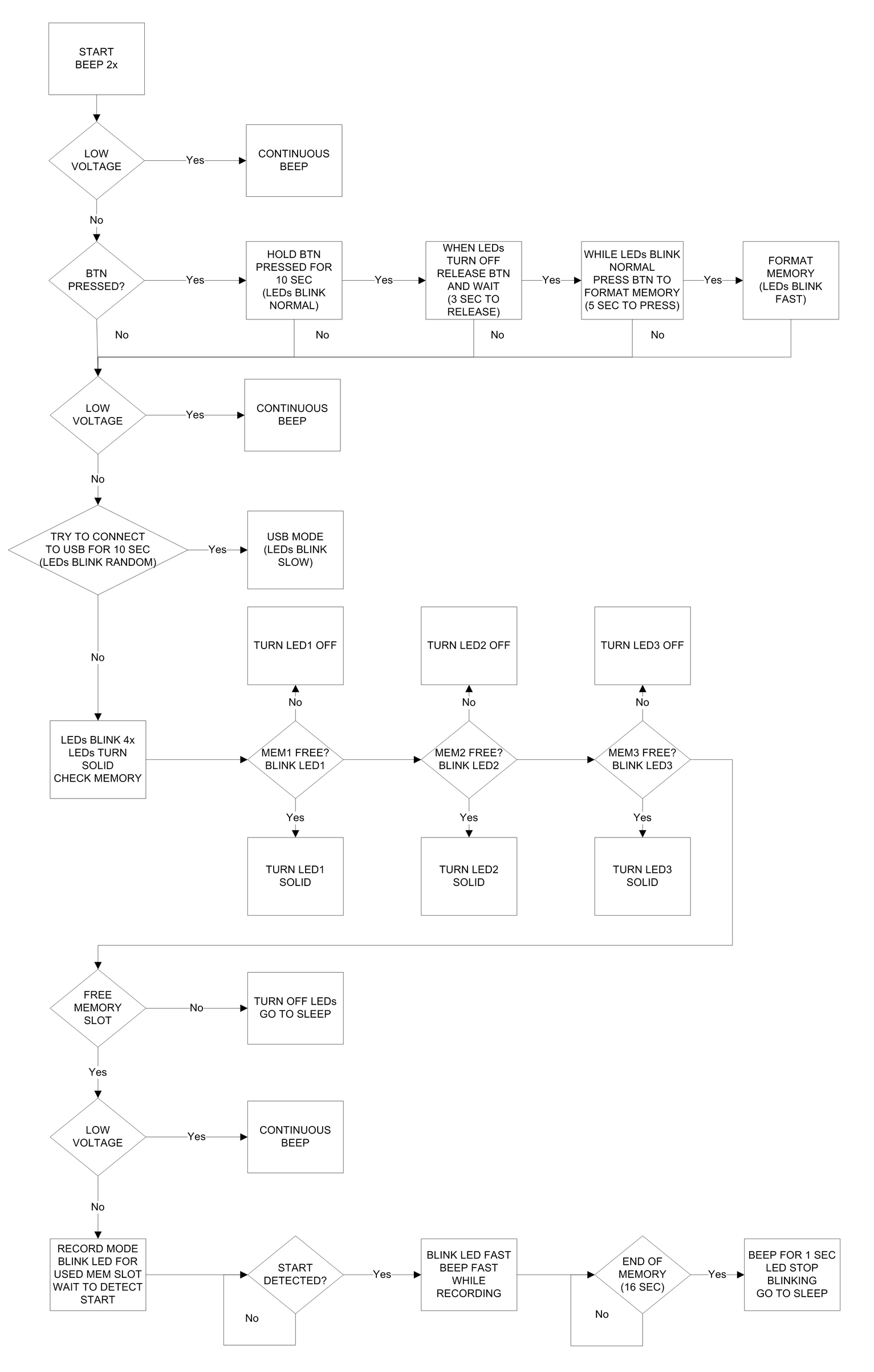
After that I tested all modules and it worked fine. So the next step was to think about the firmware logic and to write the finished firmware. This is the logic diagram:
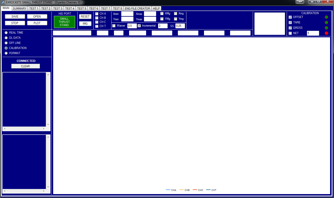
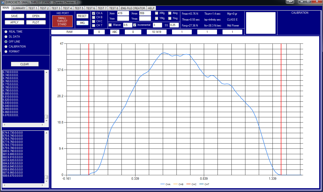
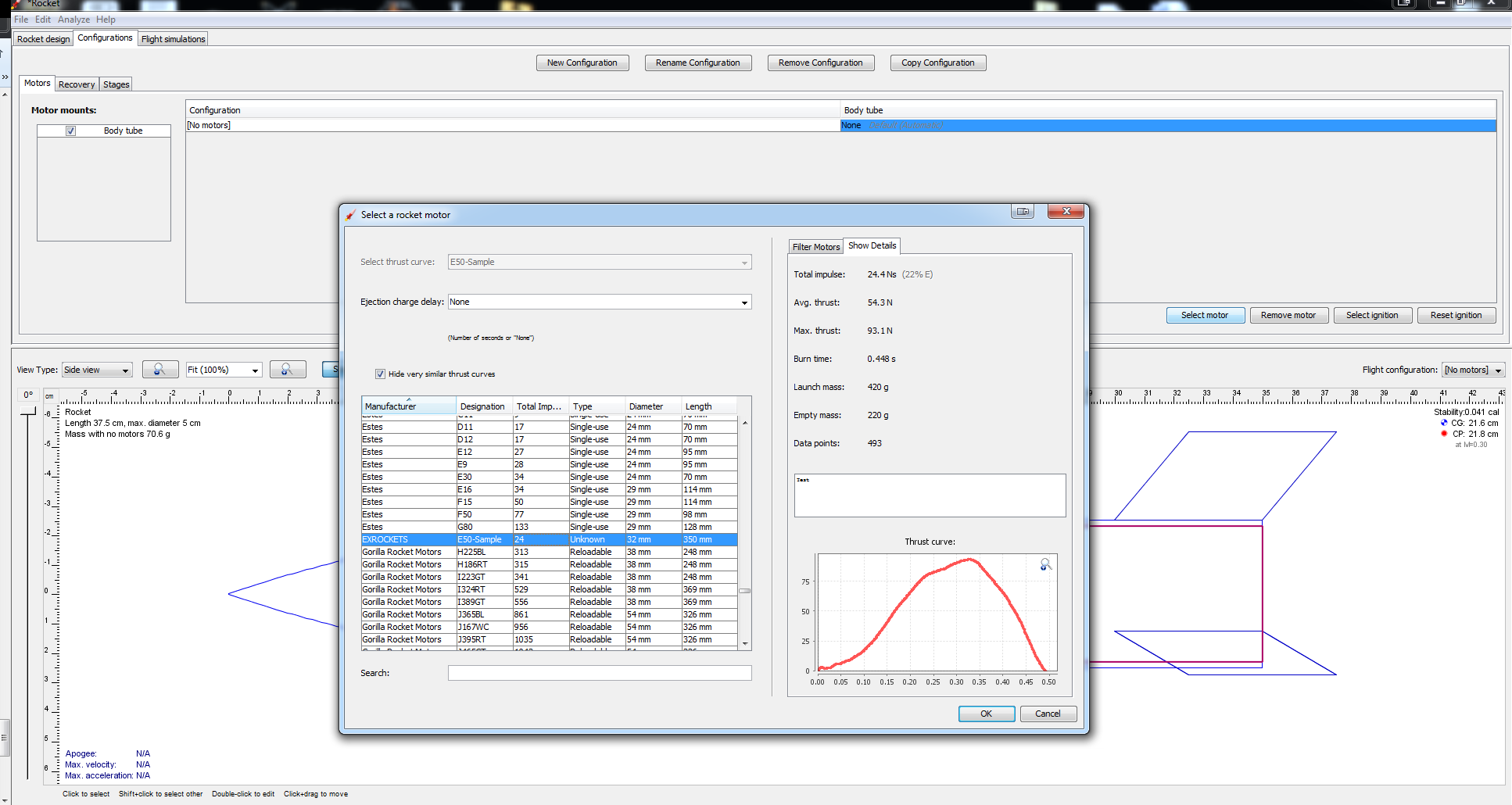
Because this DAQ system does not have a display it needs a host application on the PC side. Therefore I made the following host program that gives you control over the DAQ system as well as the possibility to calculate the downloaded data (full description and help is available in the program).
This is basically the same host application that I made for and described in ROCKET THRUST STAND DAQ SYSTEM WITH GLCD but adjusted for this particular DAQ, therefore data files created by either application can be opened by both programs while in OFF LINE mode:
You can create also an ENG file which is the RockSim file format to hold the thrust and motor information and can be used in various programs like RockSim and OpenRocket.
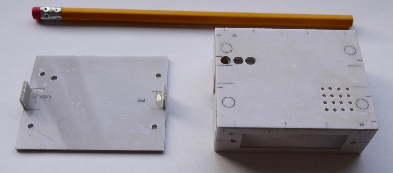
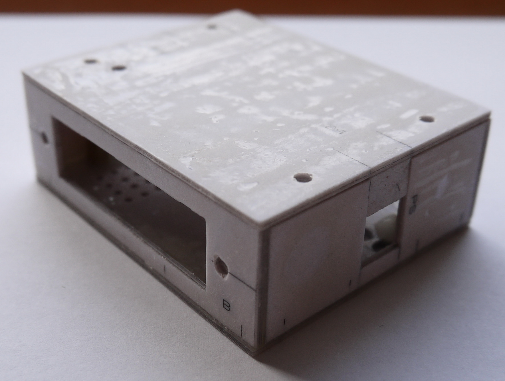
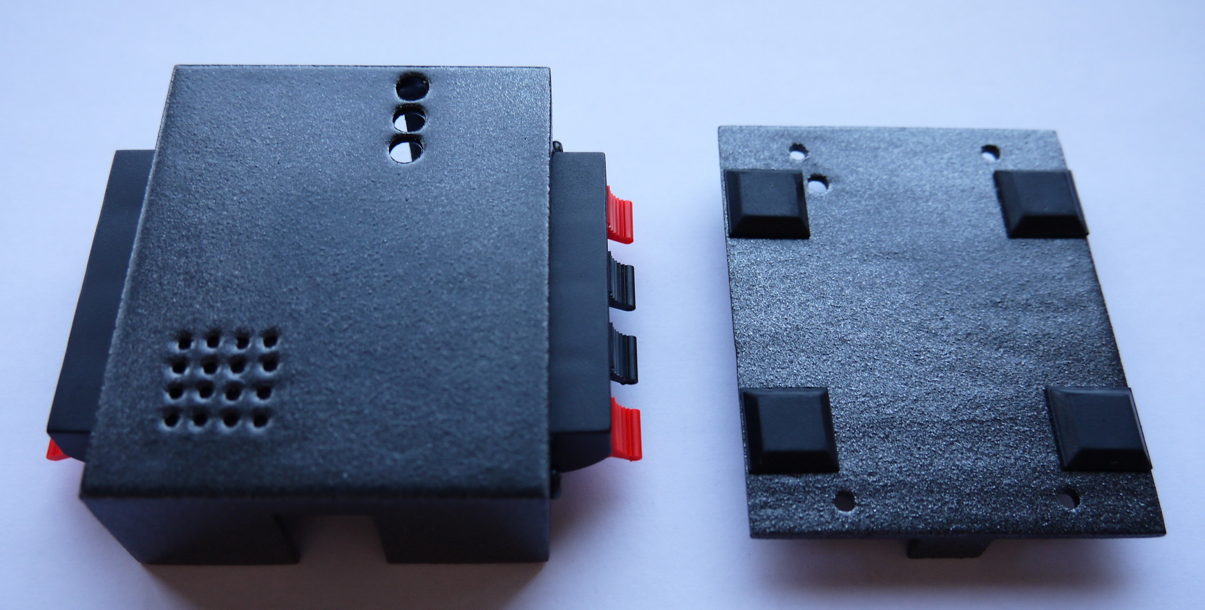
Finally I made a case for the small DAQ system. The case was made from paper and epoxy the same way as I described more in details here.
This is a basic demonstration video how to work with the small DAQ system. The video was made with the JETEX/RAPIER ROCKET MOTOR THRUST STAND but they are basically the same:
EDIT: My initial intention was to use the thrust stand with calibration weights of at least 1 kg which allows you to use 1kg load cells. But I have been already asked several times if the thrust stand DAQ can be used for micro motors where thrust in the gram-range will be measured.
To do that you will have to use a load cell, rated less than 1 kg (for example 100gr, 200gr or 500gr load cells). However in this case you will need calibration weights of less than 1 kg. To implement this function I had to make a minor modification in the firmware as well as in the software application. Now you will have the option of choosing what is the measurement unit used for calibration i.e. kilograms or grams and the calibration weight range is either from 1gr to 255gr or 1kg to 255kg.
The new application and firmware can be found at the bottom of the page.
SMALL_THRUST_STAND_APPLICATION 1.00
SMALL_THRUST_STAND_CADCAM_PCB_FILES
SMALL_THRUST_STAND_HID_FIRMWARE 1.02
CASE_DRAWINGS
Very nice unit. Any chance of purchasing a finished unit? I am in Colorado, USA. Best wishes,
Ed
Hello Ed,
Yes, I’ve made some additional units to give out to friends, however they miss the paper/epoxy case – it’s too much work :). I didn’t make the DAQ system for profit so the cost is only for the PCB and the parts I bought (total about 5$) + shipping from Canada with CanadaPost.
If you are still interested, please contact me on my e-mail.
Regards
I was just wondering what the chances might be that the load cell in a common digital fishing scale could be hooked up to this board and used to read loads directly to a PC. I’ve got a fish scale on order so I don’t know what the conponents look like inside. Wondering if you’ve ever taken a fish scale apart and looked inside?
John Boren
Hello John,
The excitation voltage supplied by the DAQ system is 5v and all load cells that I have seen accept higher voltages so in general this shouldn’t be a problem.
As for the shape of the load cell inside the scale, I have never opened such scales and can’t say.
The software for the board runs on my 5 year old Home PC but the board is not reconized. Since I wanted to use one of my Very Old laptops anyway this didn’t matter. My Lap Tops are real old Dell Latitudes Cpi running on Windows 98 and IE 6.0. Net Frame 2.0 is the highest version I can run on Windows 98 and your software reguires Net Frame 4.0. Not sure what to do now.
By the way I got the digital fish scale in today. It has real nice load cell in it that has a red, black, white and green wire coming off of it that I can splice a connector onto easily enough. Hopefully it will run on 5 Volts instead of the 3V that the battery supplies to it.
Hello John,
I guess your PC is an Intel based one? There was an issue because of the non-standard USB controllers on some Intel motherboards, The board should be normally recognized on AMD systems though.
Anyway it is fixed now and it works under both AMD and Intel systems – in few days I will send the new chips to Ed so he can forward it to you with instructions.
As for the Win98 based Laptop – I don’t think it will work because of the HID USB drivers but I will run few tests here and let you know.. Still you can record up to 3 tests in stand-alone mode and download them on your Desktop PC.
I believe these Dells Can run Windows NT. If I can find an old install CD for this operating system I will try that as well.
Good afternoon! Is it possible to buy a ready-made device? I will be grateful to you.
By the way, my PC has a AMD board and processor in it. The error message says it needs a driver for this USB device.
I believe this is the device ID for your board connected to my machine.
Unknown Device USB\VID_0000&PID_0000\5&24368E9D&0&5
What is the Operation System? All systems after WinXP have a generic USB driver that doesn’t require installation. Try a different Can you send me screenshots?
Also you can copy the mcHID.dll file from the program folder to your windows\system32 folder and reset the device.
Do you have any pc boards for this you could part with. I have been looking for a way to test my sugar motors and I like this project. I appreciate any help you could give. If so give me the info at my email. Thanks!