This is a joint project between me and –vega- (Yordan) for making a very small thrust stand that will be used for testing Jetex and Rapier like motors. Those motors typically have burn time between 12 to 20 seconds while producing thrust in the grams range.
DAQ System:
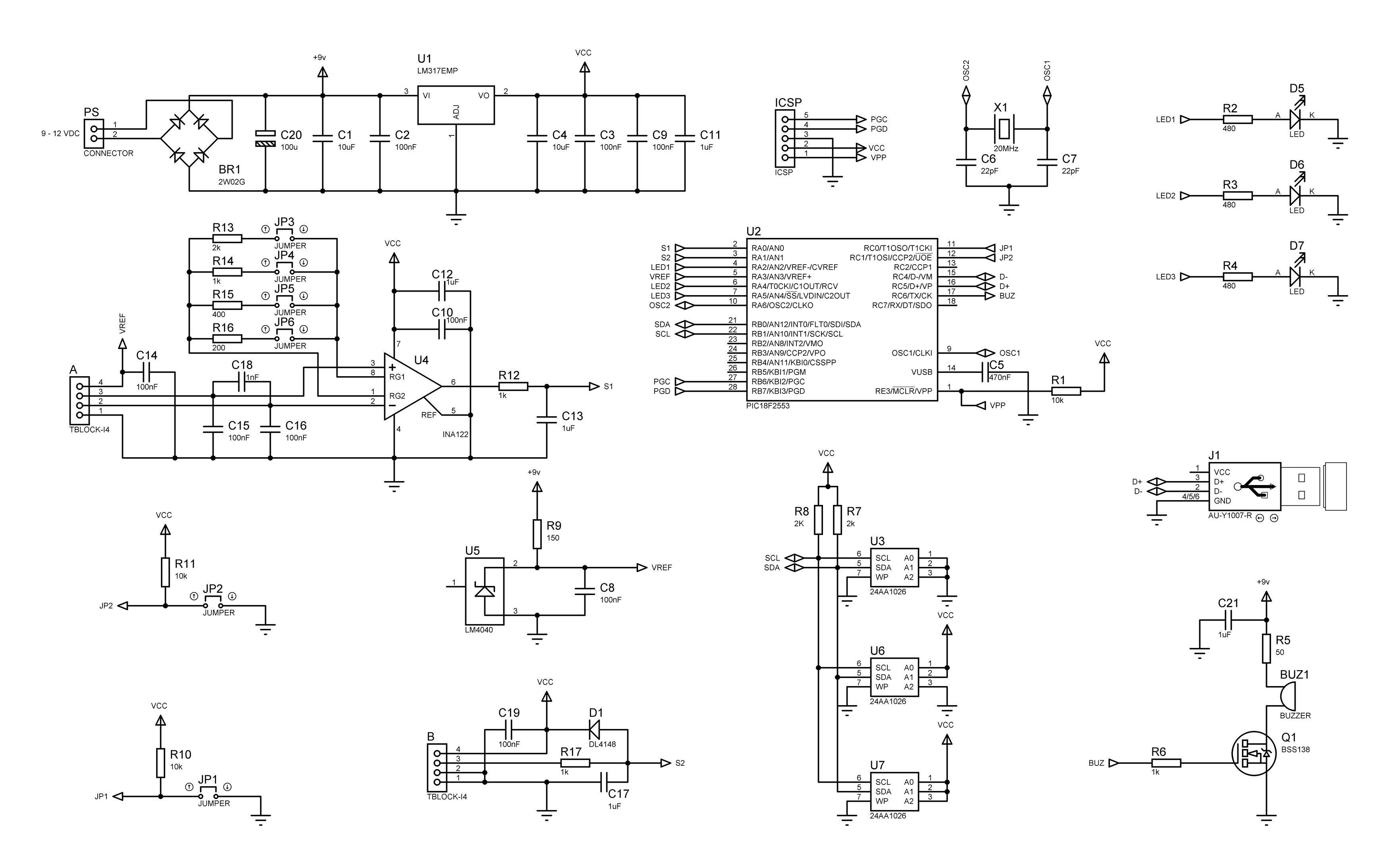
The electronic part of the project is actually a modified version of the ROCKET THRUST STAND SMALL DAQ SYSTEM however this DAQ system has:
– Memory for 3 tests
– Maximum duration of 32 seconds per test
– Capability for simultaneously recording the both channels
– Recording speed of 1000 samples per second per channel
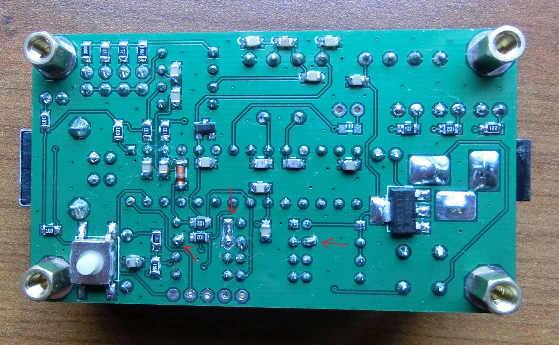
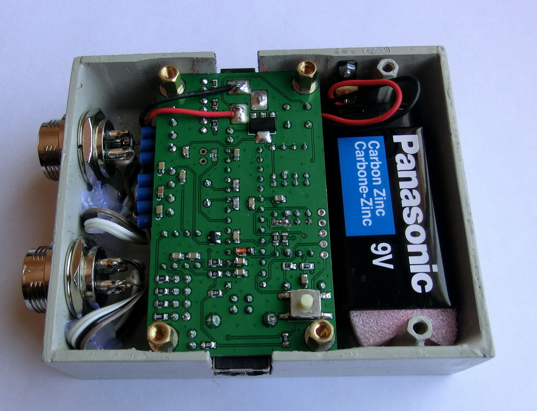
In order to accommodate the requirements for speed and time I replaced the existing memory banks of 256 Kb with 1 Mb chips:
However the 24AA1026 I2C memory from Microchip has slightly different addressing and no internal pull-down resistors for the WP pin (or at least nothing is mentioned about that in the datasheet). Therefore I had to modify a little bit the current PCB – solder the WP pin to ground, and change the addressing on one of the chips. Changing the memory address is actually cutting the pin from the ground and soldering it to the nearest pin to connect it to the positive supply.
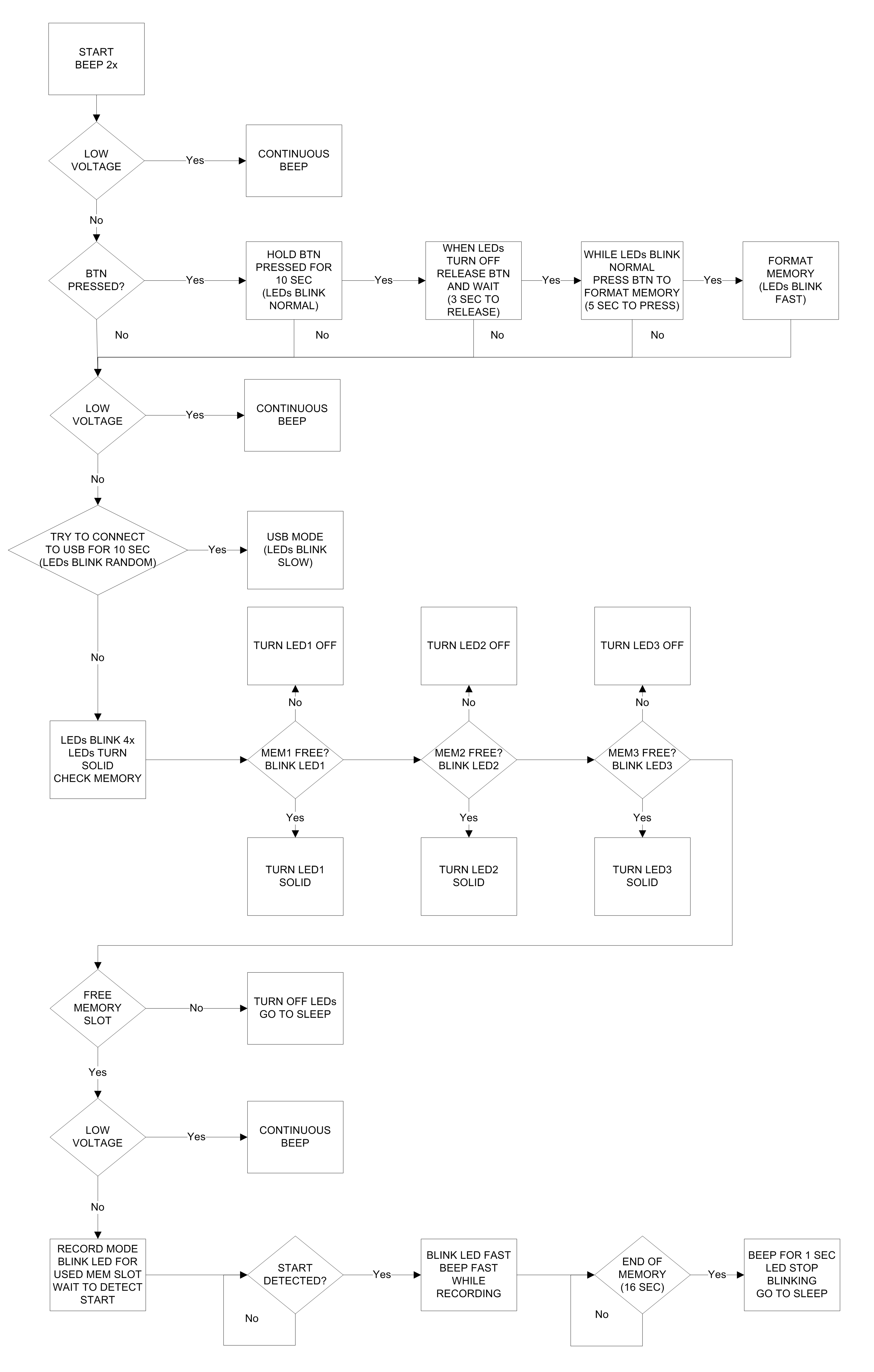
The flow chart remains the same:
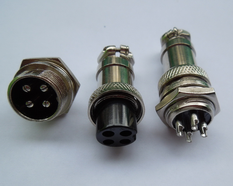
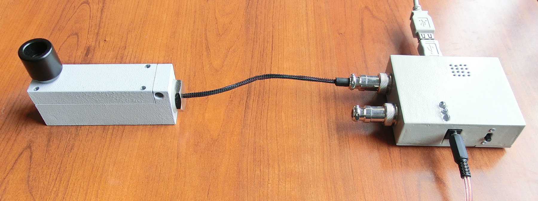
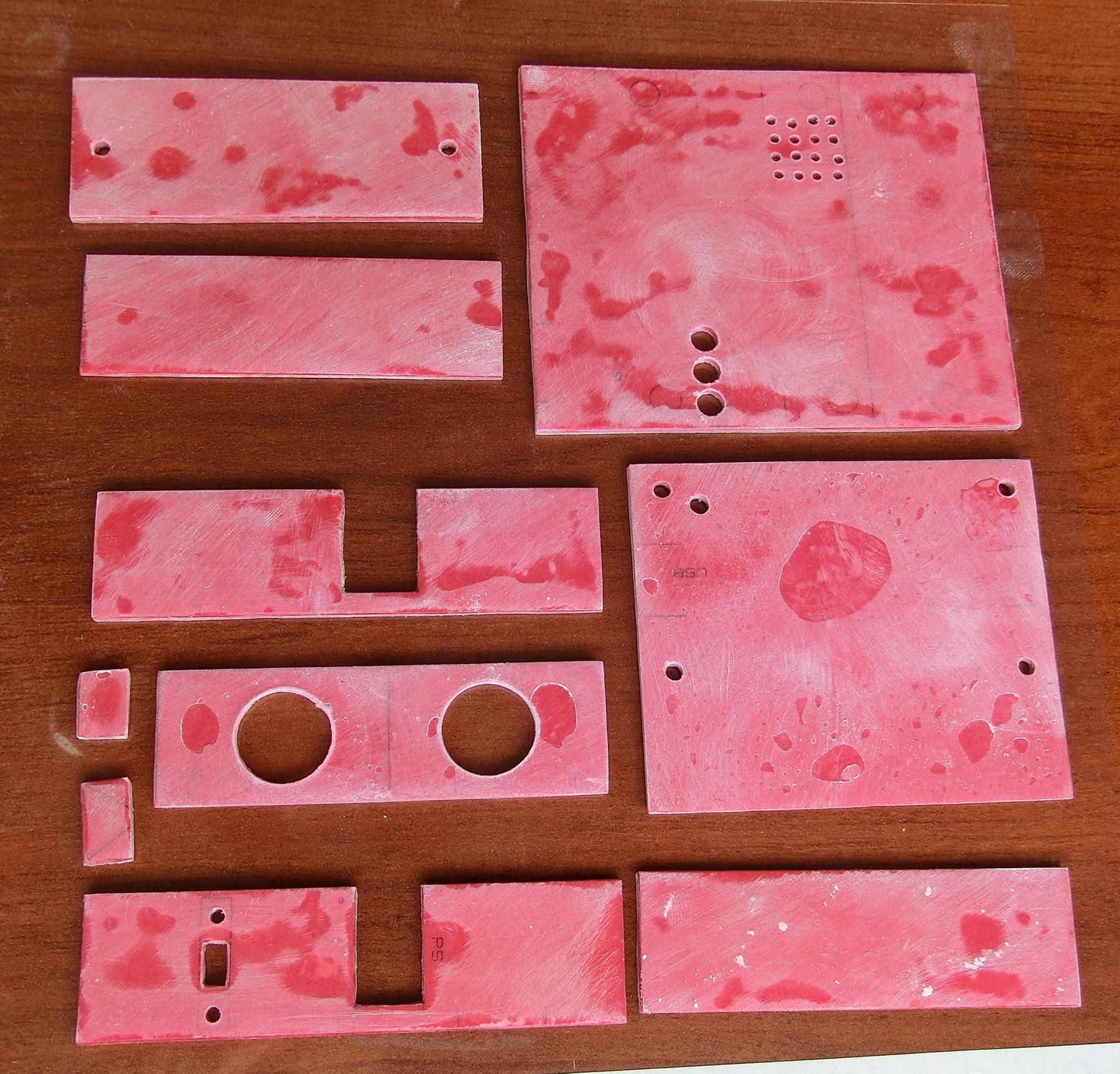
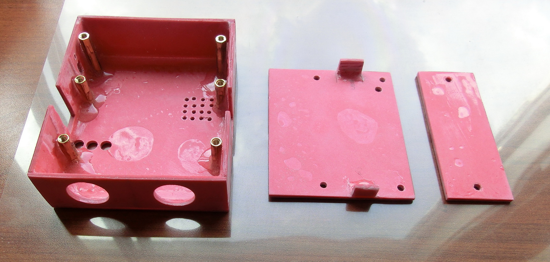
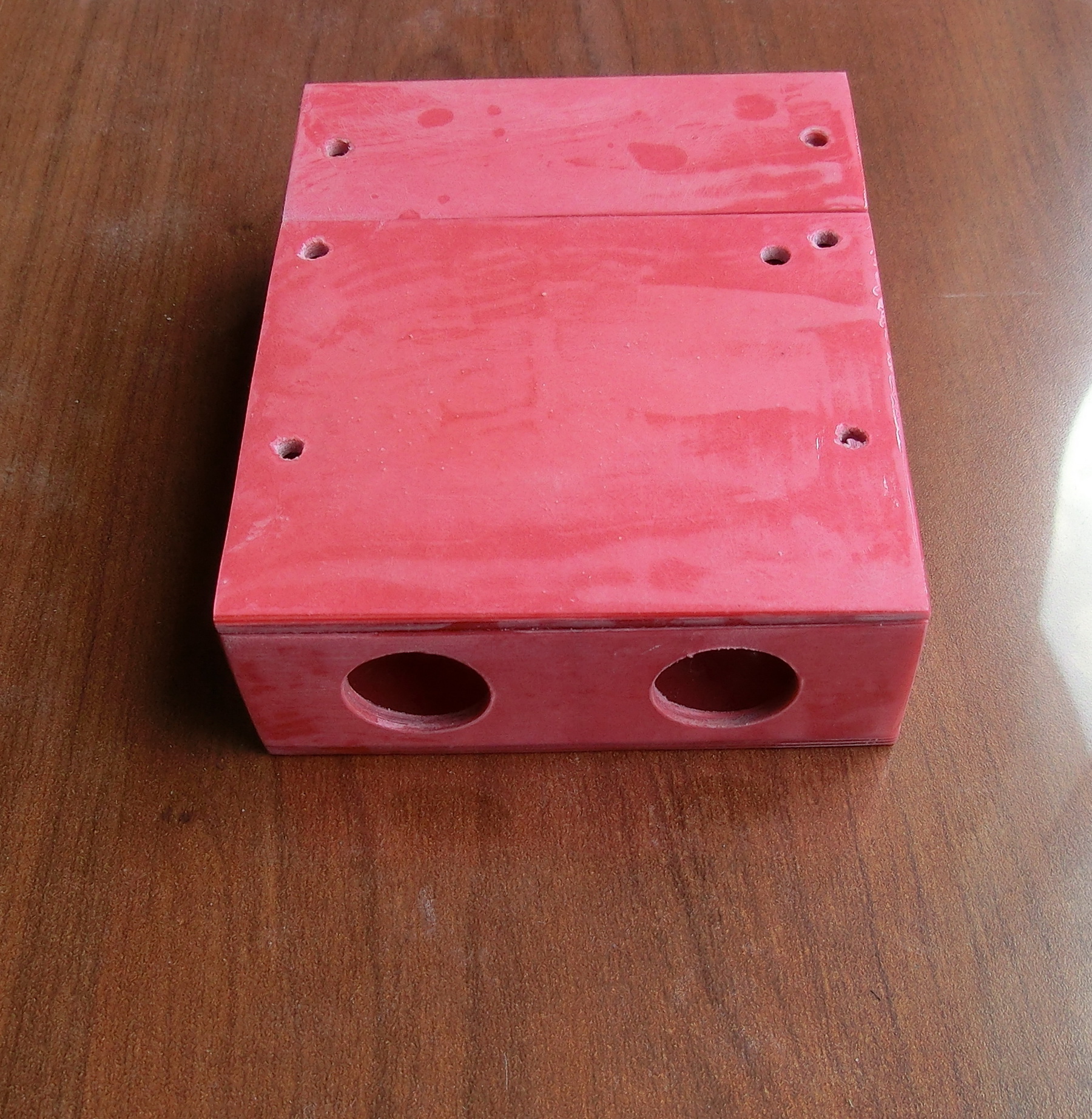
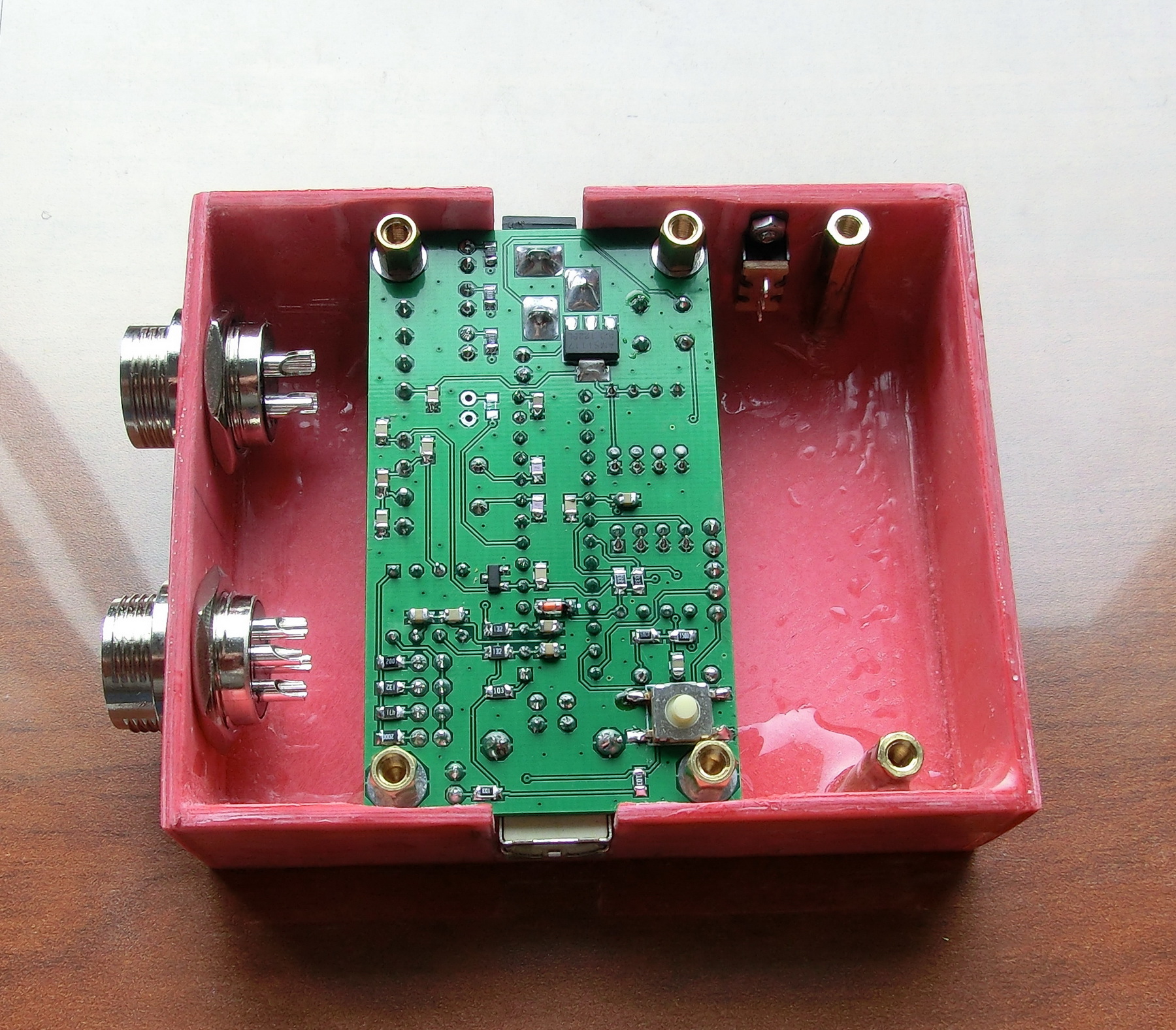
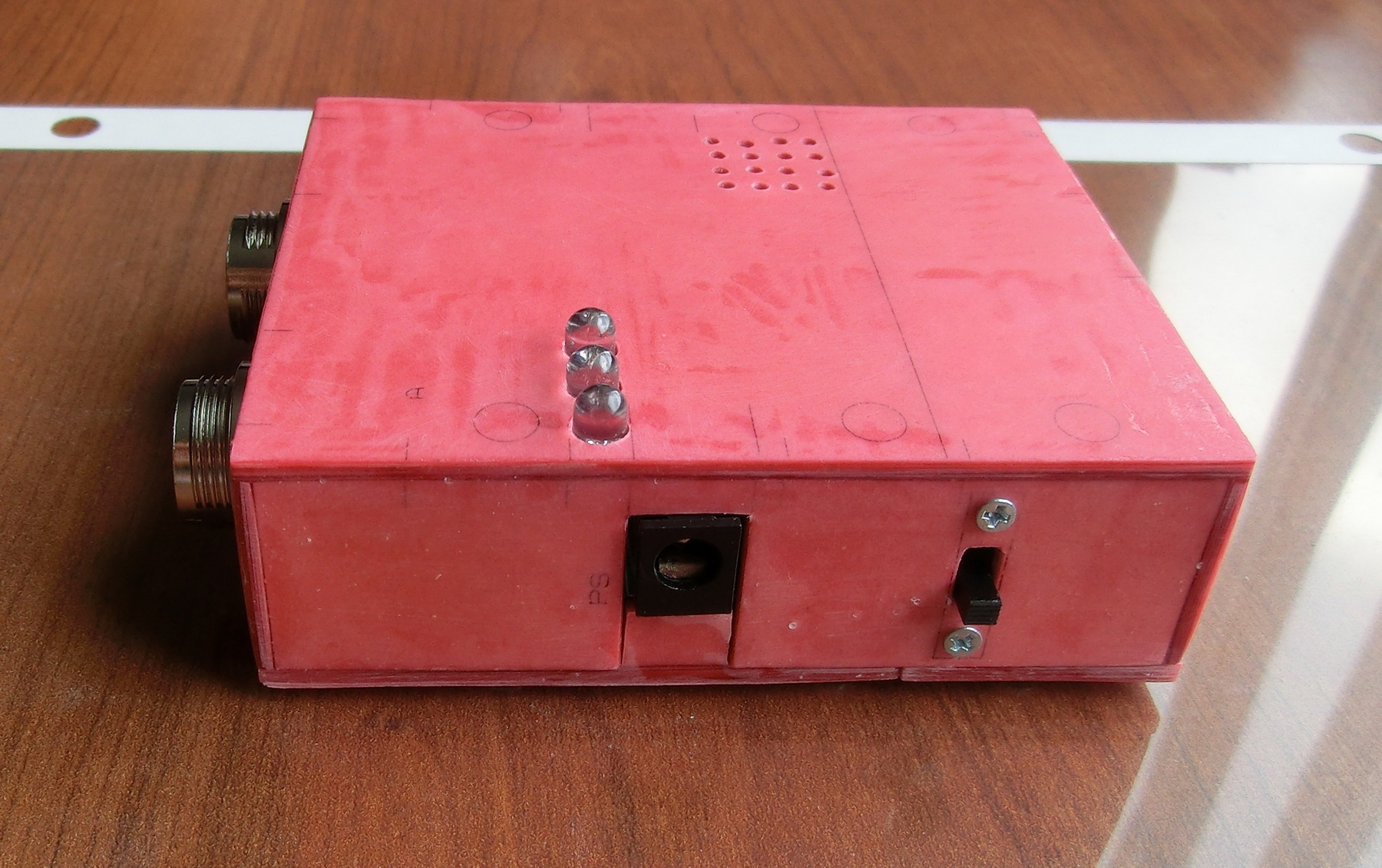
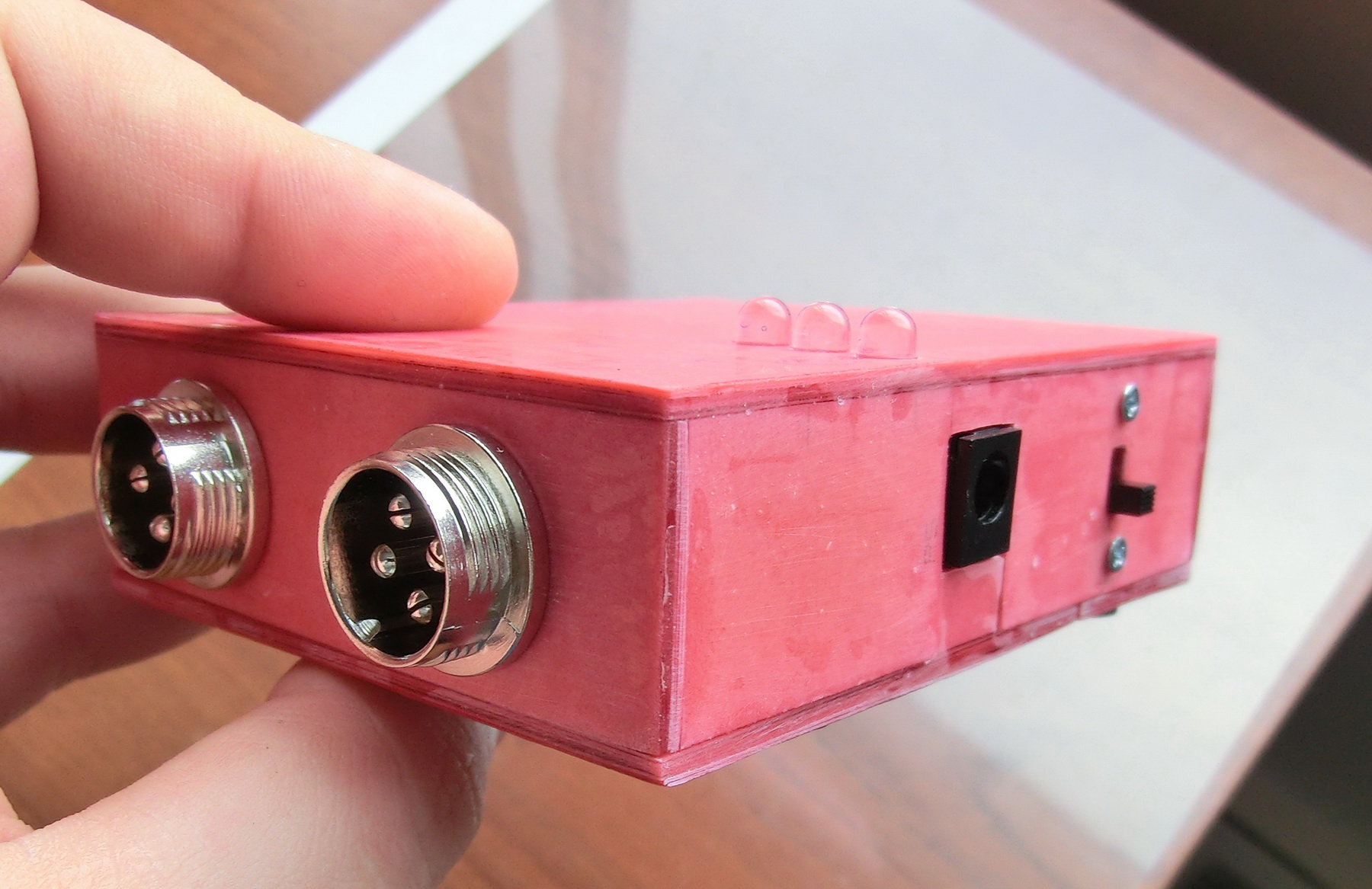
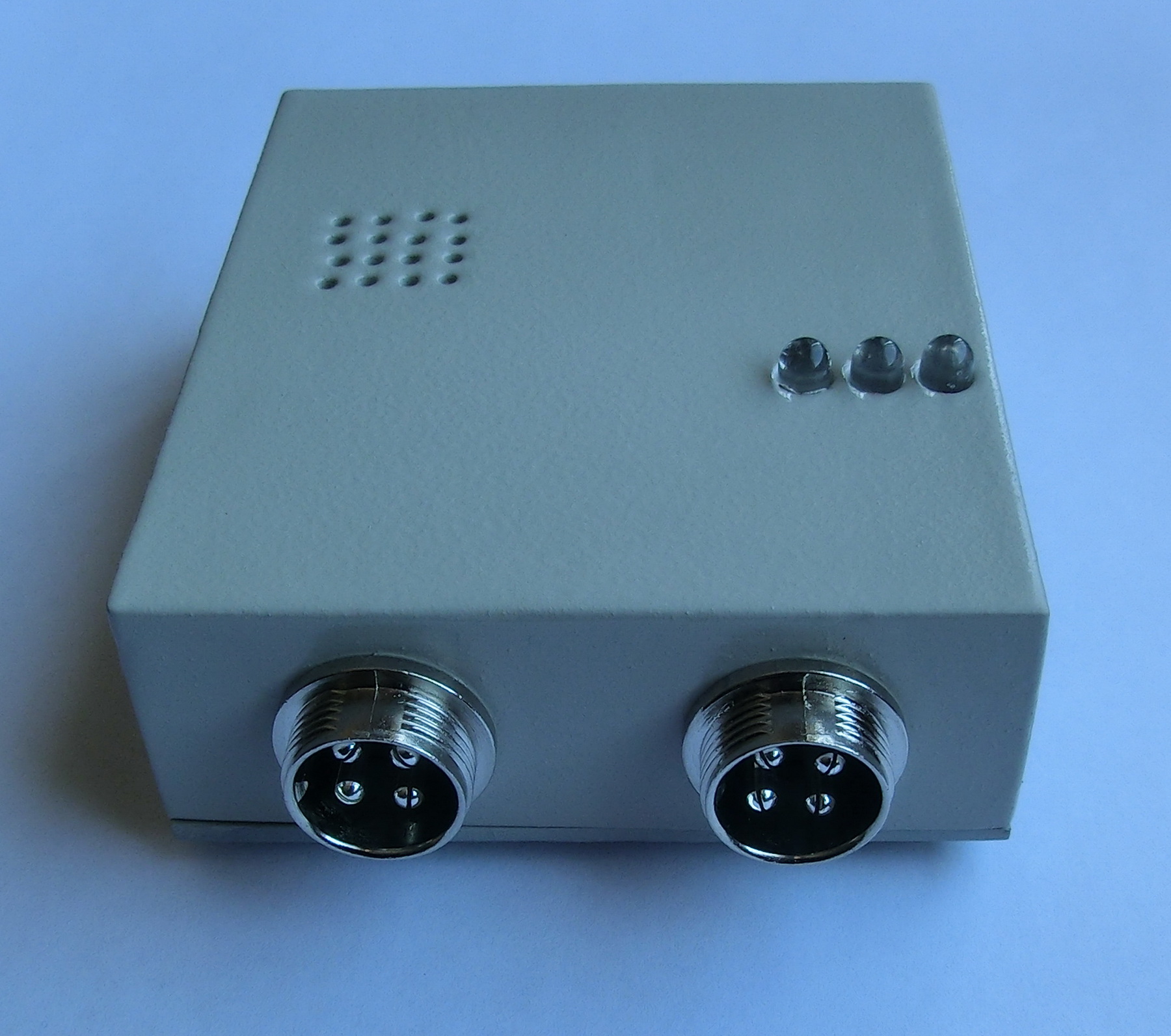
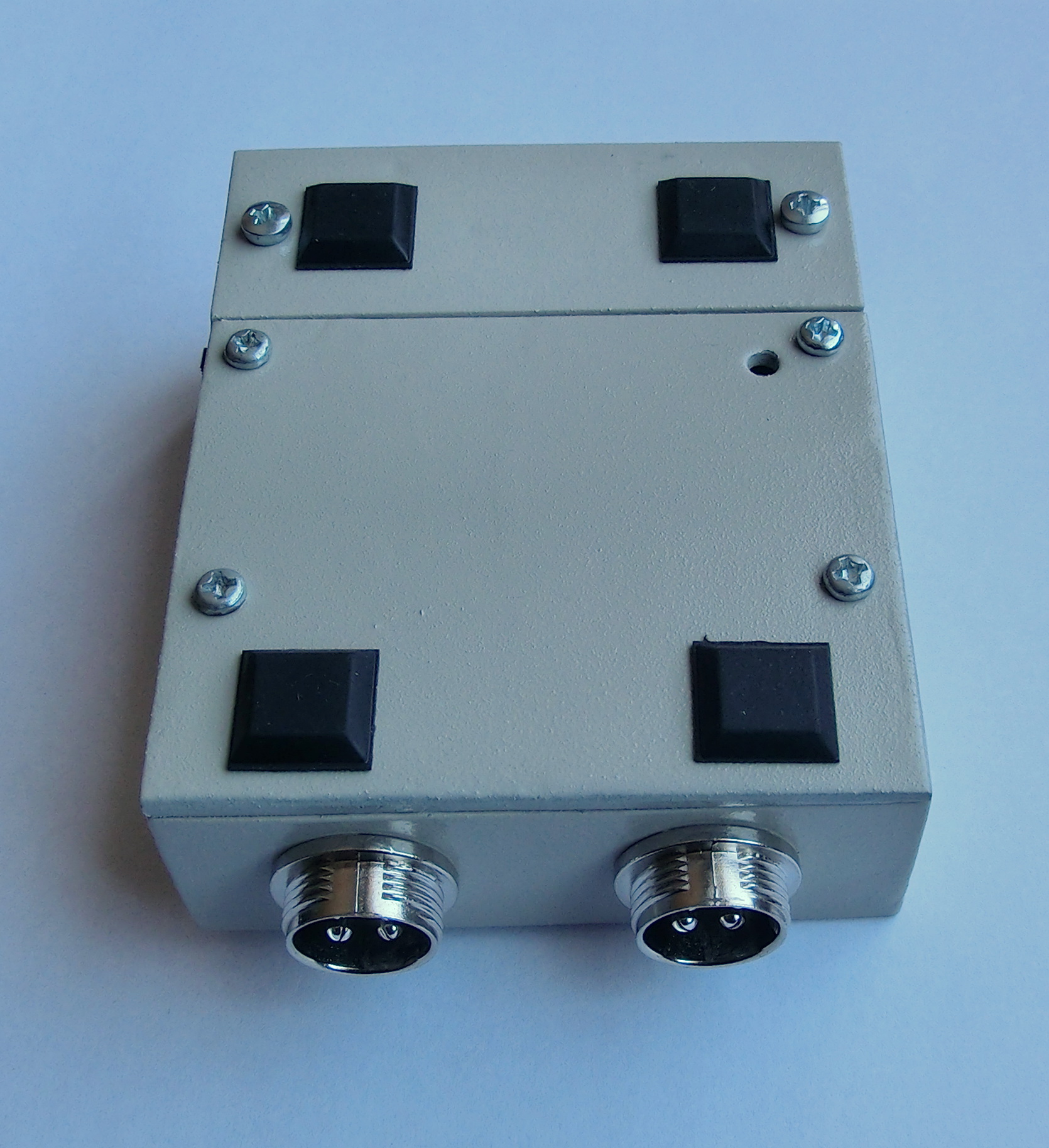
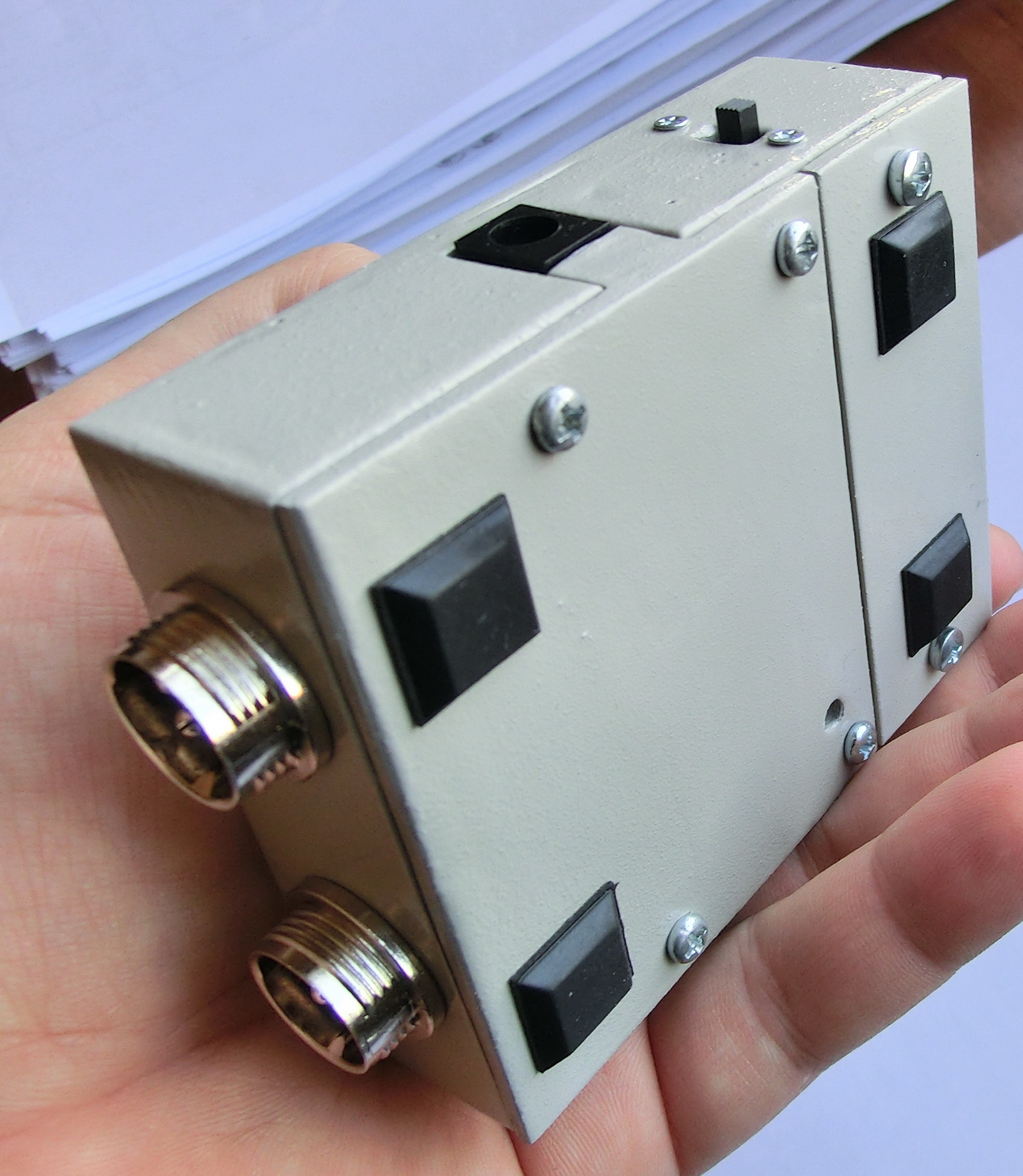
Once that was done the next step was to make a good case for the DAQ system. For this case I decided to use the same Epoxy/paper laminate as before. Only this time instead of the usual push-down connectors I used the following 4 pin chassis connectors. Also in this case I left place for a 9 volt battery.
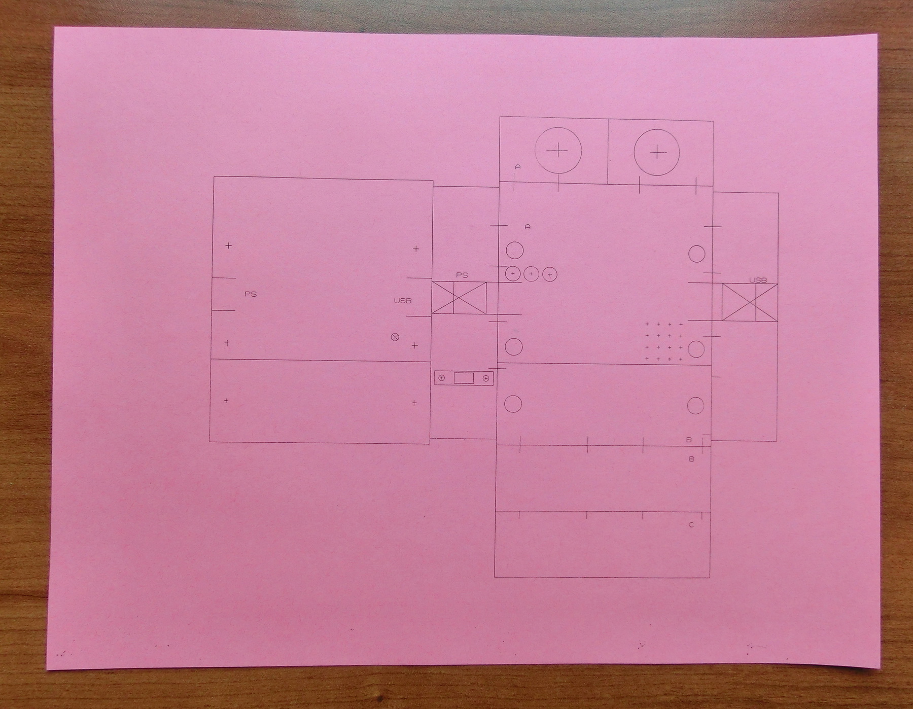
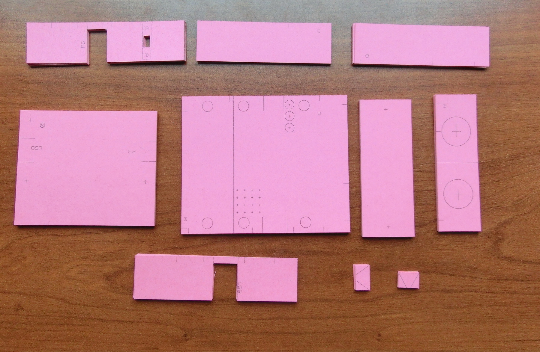
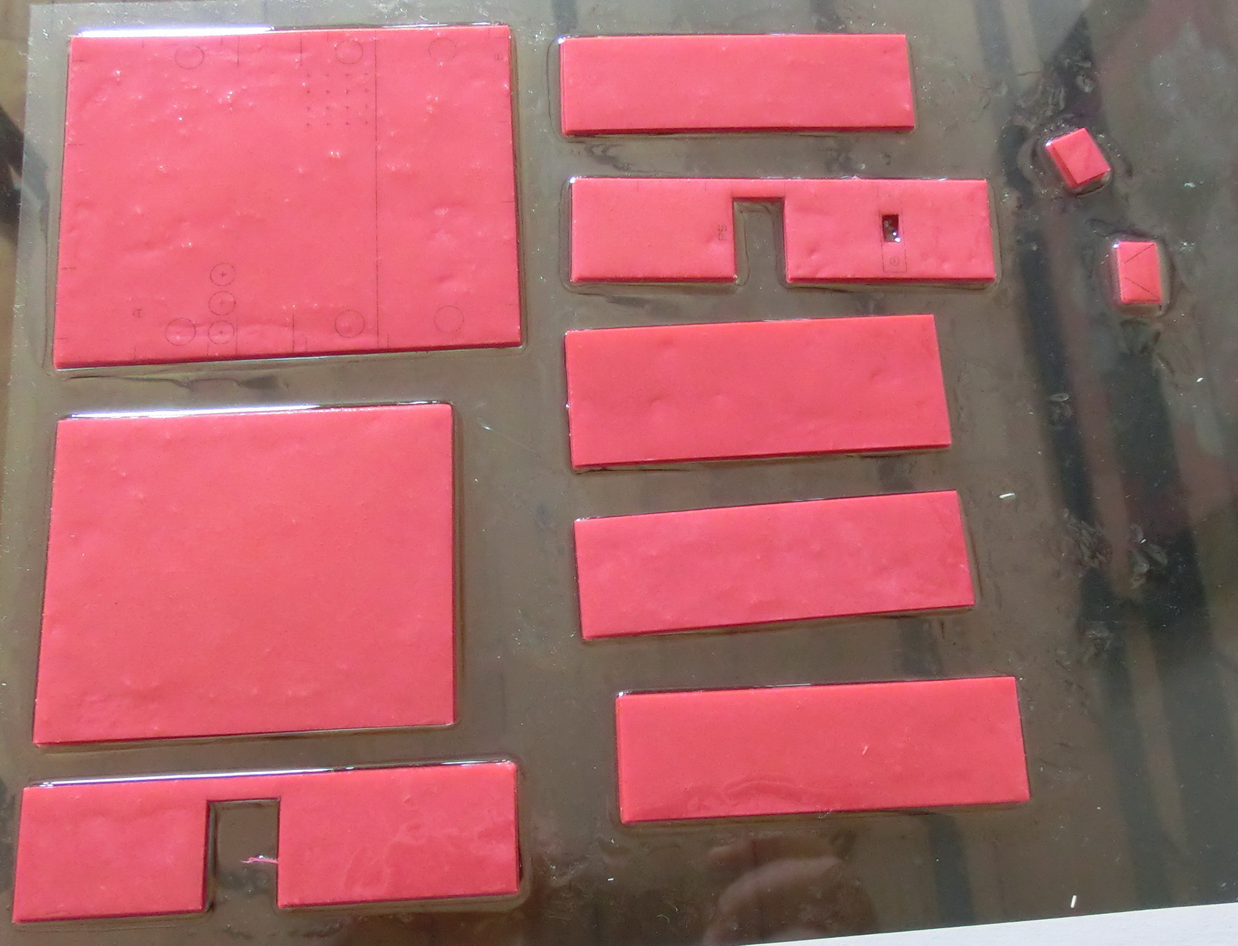
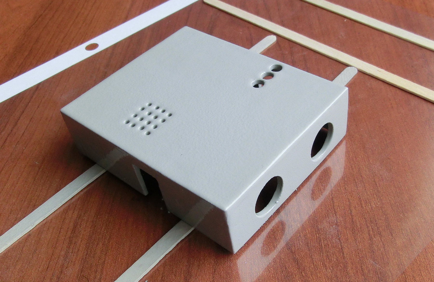
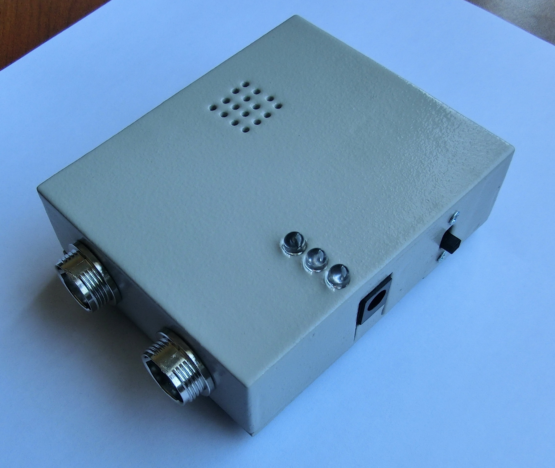
So here are few photos of the entire process of making the box. First I started by drawing and printing the box parts. Then I cut them out with a paper knife and a ruler. Next I laminated them with epoxy. Once the epoxy cured, I drilled the holes and sanded the parts. After that I glued the parts with a 5 minute epoxy and once everything cured it was time to check whether all parts fit. Finally when all was done I put few layers of paint to protect the case.
Hardware Stand
I have to say that –vega- made a true masterpiece here.
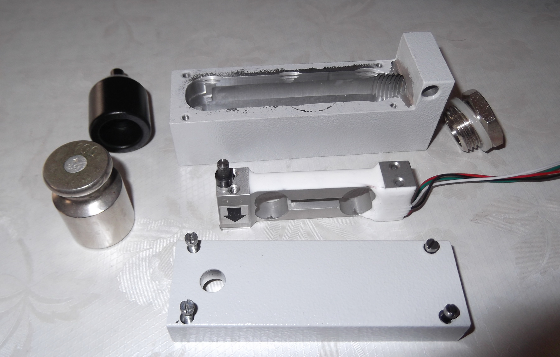
The load cell is 300gr load cell with 1mV/V output and excellent linearity.
Because this is very sensitive sensor the stand was designed so that it will provide maximum protection for the load cell. He made a special base for the load cell to be mounted in. Under the load cell there is overload protection. In addition there is a special motor holder that has strong magnet in it. This holder serves for three purposes:
– First it will allow you to safely mount the motor in it and then place the holder with the motor over the load cell. If you try to mount the motor directly on the cell you can push it too hard and permanently damage the load cell – remember this sensor is only rated for 300 gr.
– The holder will provide the necessary weight to pre-load the sensor in order to go out of the initial non-linear diapason.
– And lastly the strong magnet will keep the holder in horizontal position so that you can test motors in horizontal position.
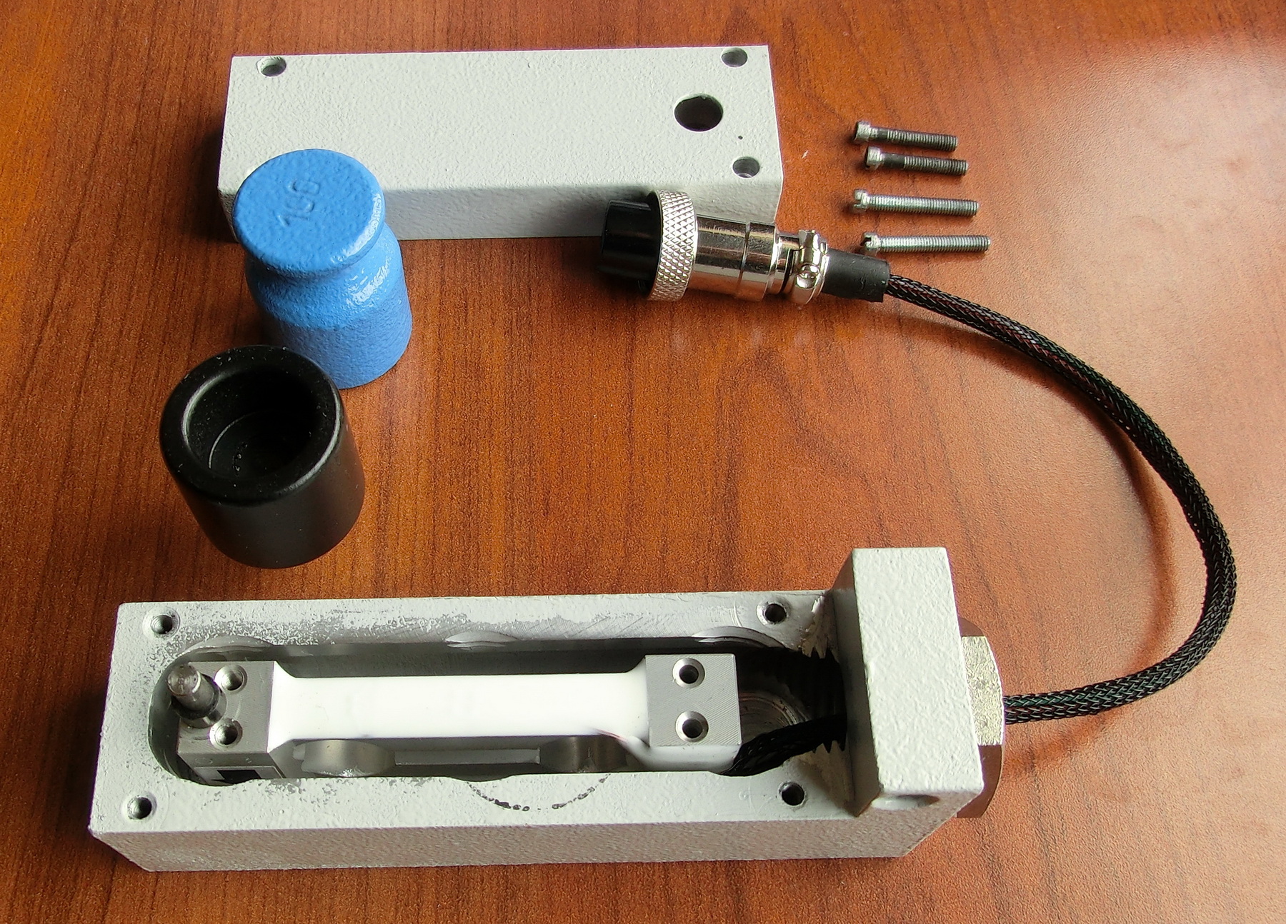
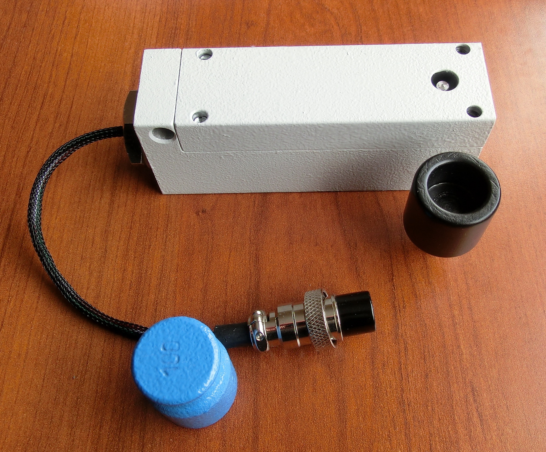
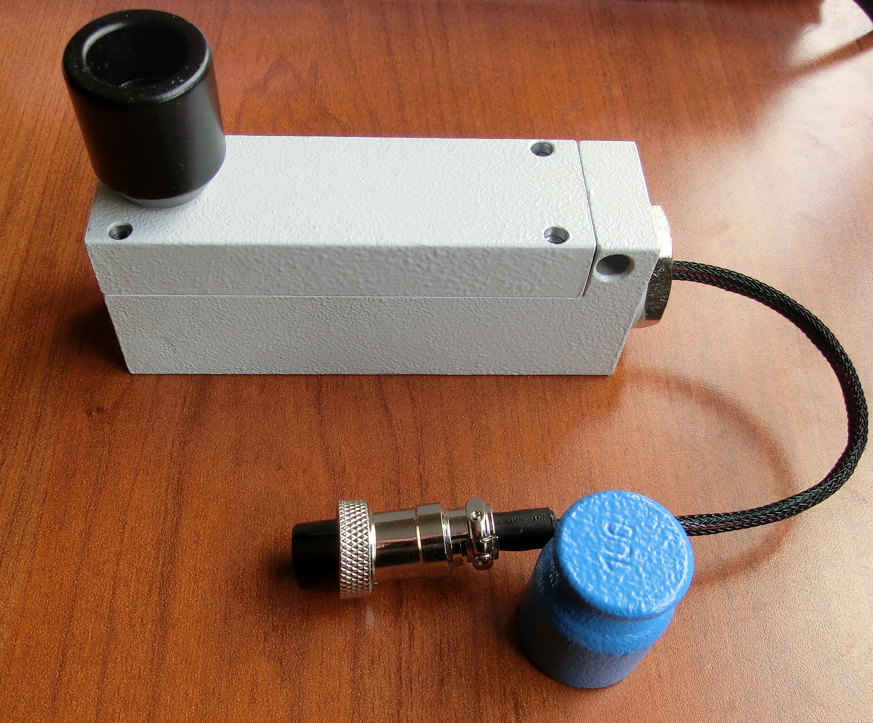
In addition to the stand, –vega- prepared a standard 100gr calibration weight that will go with the stand.So this is how the finished stand hardware looks like after putting the connector and the complete system:
After finishing the electronics and the hardware I modified the firmware and began testing the entire system.
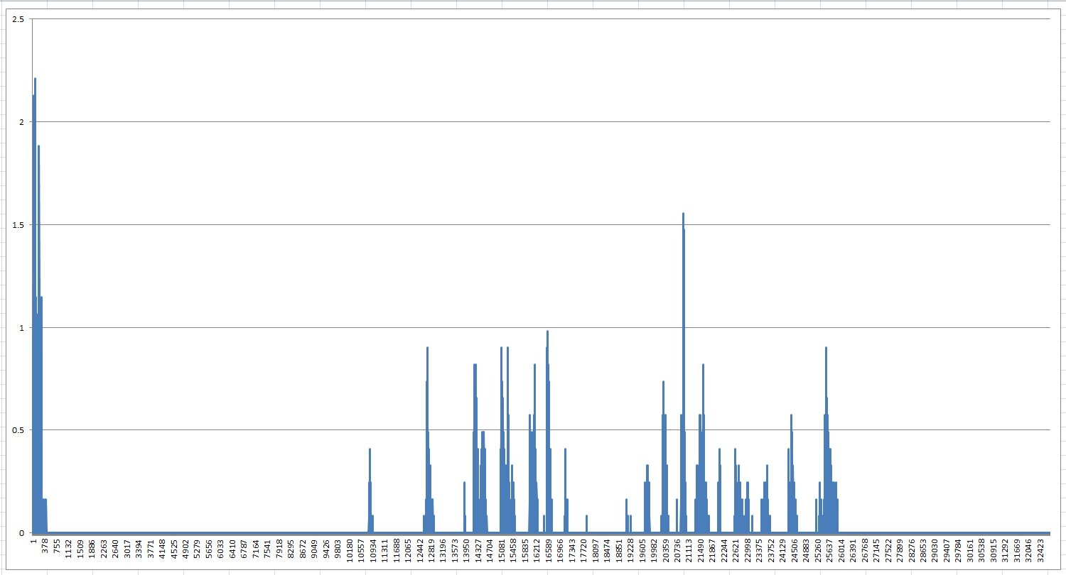
This system has very high resolution – 0.081 gr per bit. This poses certain challenges – the stand requires solid base that it has to be placed on. In my home for example I have wooden floors and when I move around there are small vibrations that generate changes in the force with which the holder pushes down the load cell. These forces are only fraction of the gram but because of the high sensitivity and speed of the DAQ system those changes are picked up by the DAQ system and trigger the recording algorithm. This is a MS Excel graph with the force generated in the load cell when I jumped a bit then I stayed calm and then I walked around in the room over the wooden floor. Vertical scale shows the force in grams and the horizontal is time in seconds.
So in order to prevent unwanted triggering I lowered the trigger sensitivity by slightly modifying the firmware trigger algorithm. Still if I jump in the room it will trigger it but at least the DAQ will not be triggered by simply walking around.
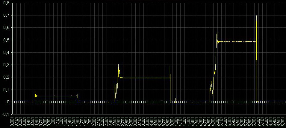
Also the PC host program needed some adjusting to accept calibration weights in the gram range (1 to 255 grams) and to format the new 1 Mb memory chips. I made three tests for accuracy with 8, 42 and 102 grams and the entire stand is accurate to the gram as my electronic weight scale.
This is a 8gr battery left in the holder from about 5mm height. You can see the vibration caused by the magnet until the battery settles still.
Next is 42gr tennis ball left to fall on the holder from few millimeters. Again some vibrations are recorded until the system settles.

And this is a 102gr cup I tried to put as careful as a possible over the holder – but the high speed/sensitivity system recorded everything – from little handshaking to the resonance in the cup.
 This is a basic demonstration video how to work with the DAQ system:
An important point that –vega- reminded me to mention is that because of the high speed and sensitivity of the system, the stand will record much more additional information that usually gets clipped in thrust stands. For example it can pick up vibrations and resonances during the combustion process. This is might be perceived as “noise” but it is useful information. Because you have 1000 samples per second you can smooth the graph if you don’t need that additional information by using simple smoothing filters like moving average for example.
In any case it is always better having more data points and apply some decimation than having only few data points and interpolating the missing values.
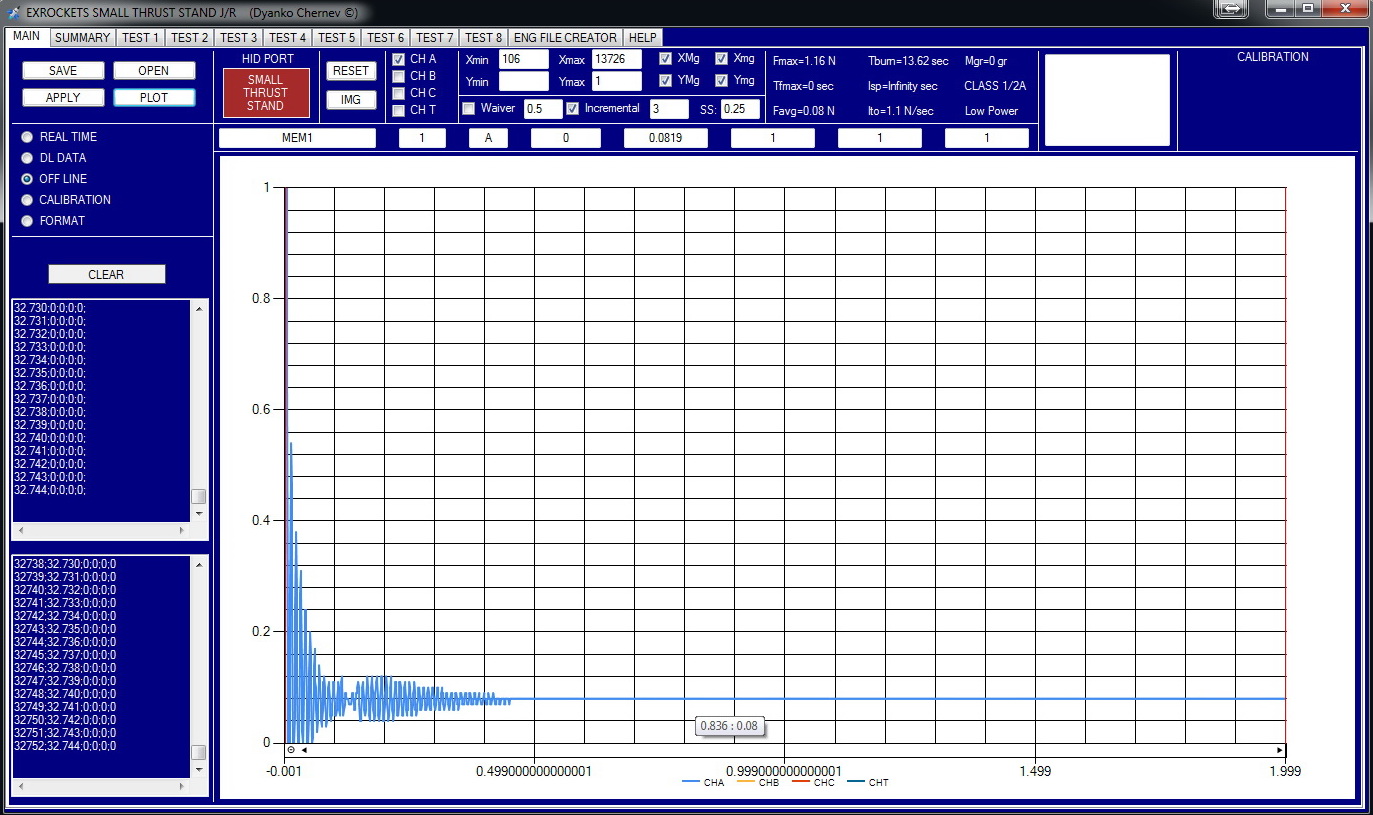
This is the DAQ system when it was tested with different calibration weights – the system is very stable and there’s no noise.
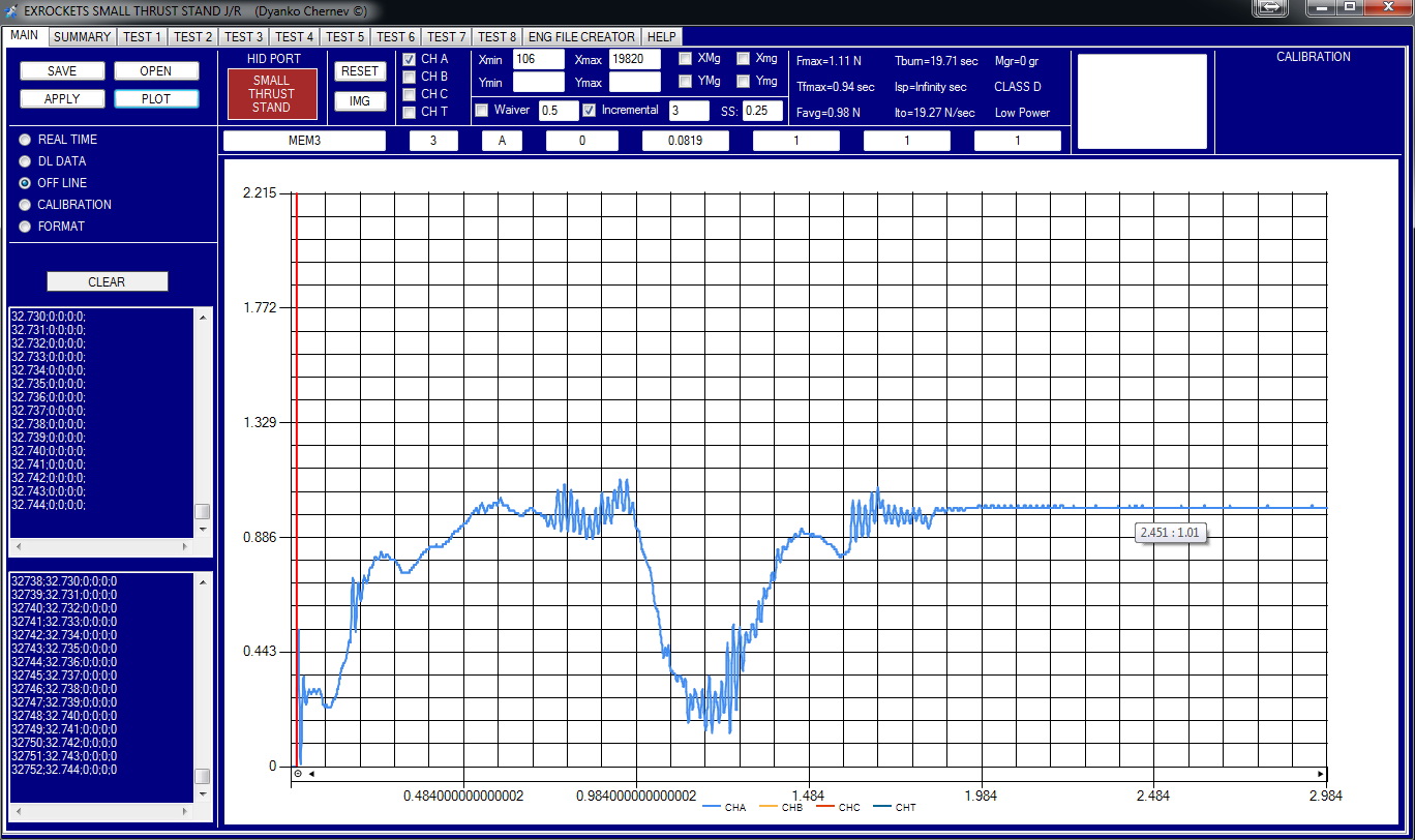
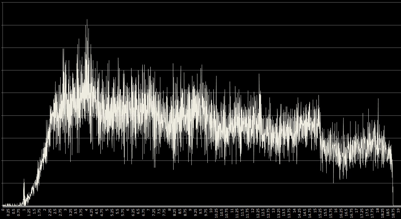
This is how a Rapier-like motor’s thrust curve looks like with all information on it – it seems that there’s quite few “noise” but in reality this is not random noise.
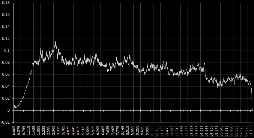
And finally for presentation purposes simple moving average was applied to smooth the graph.
MCU Firmware (hex file)
SMALL_THRUST_STAND_APPLICATION_1_MB_JETEX_RAPIER_v_1_00
Leave a Reply