This is a project is for chronograph that was purposely build for a good friend of mine to be used for accurate measuring of high speed processes.
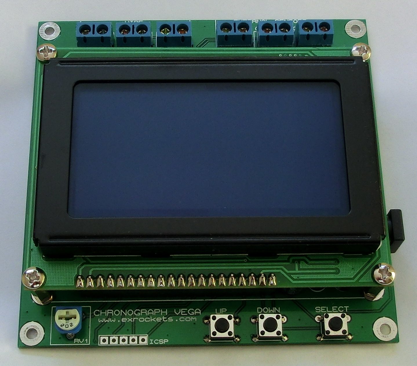
The main characteristics of this chronograph are:
- two separate timers
- minimum measuring time of 850 nano-seconds
- maximum measuring time 10 seconds
- resolution of 100 nano-seconds
- 80 nano-seconds timing error
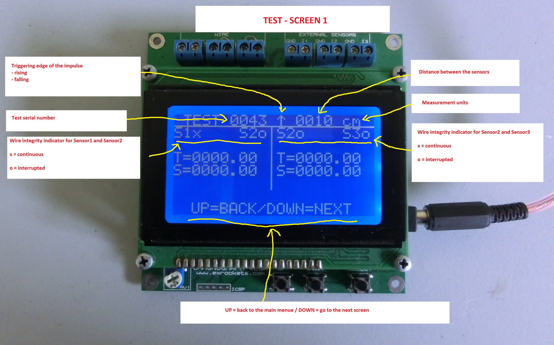
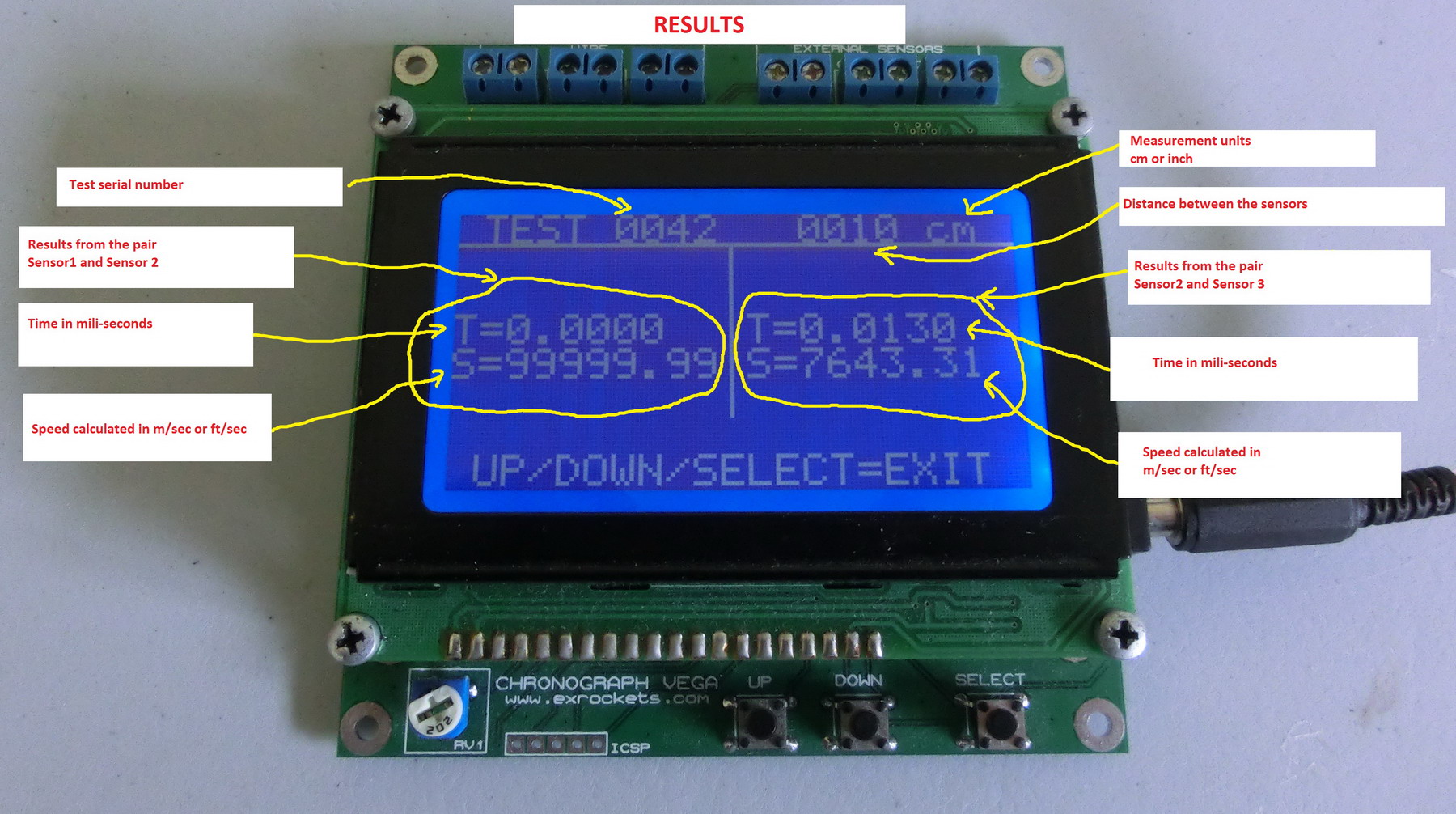
- minimum sensor distance 1 cm or 1 inch
- maximum sensor distance 10000 cm or 10000 inches
- selectable measuring system m/sec, ft/sec or mm/sec
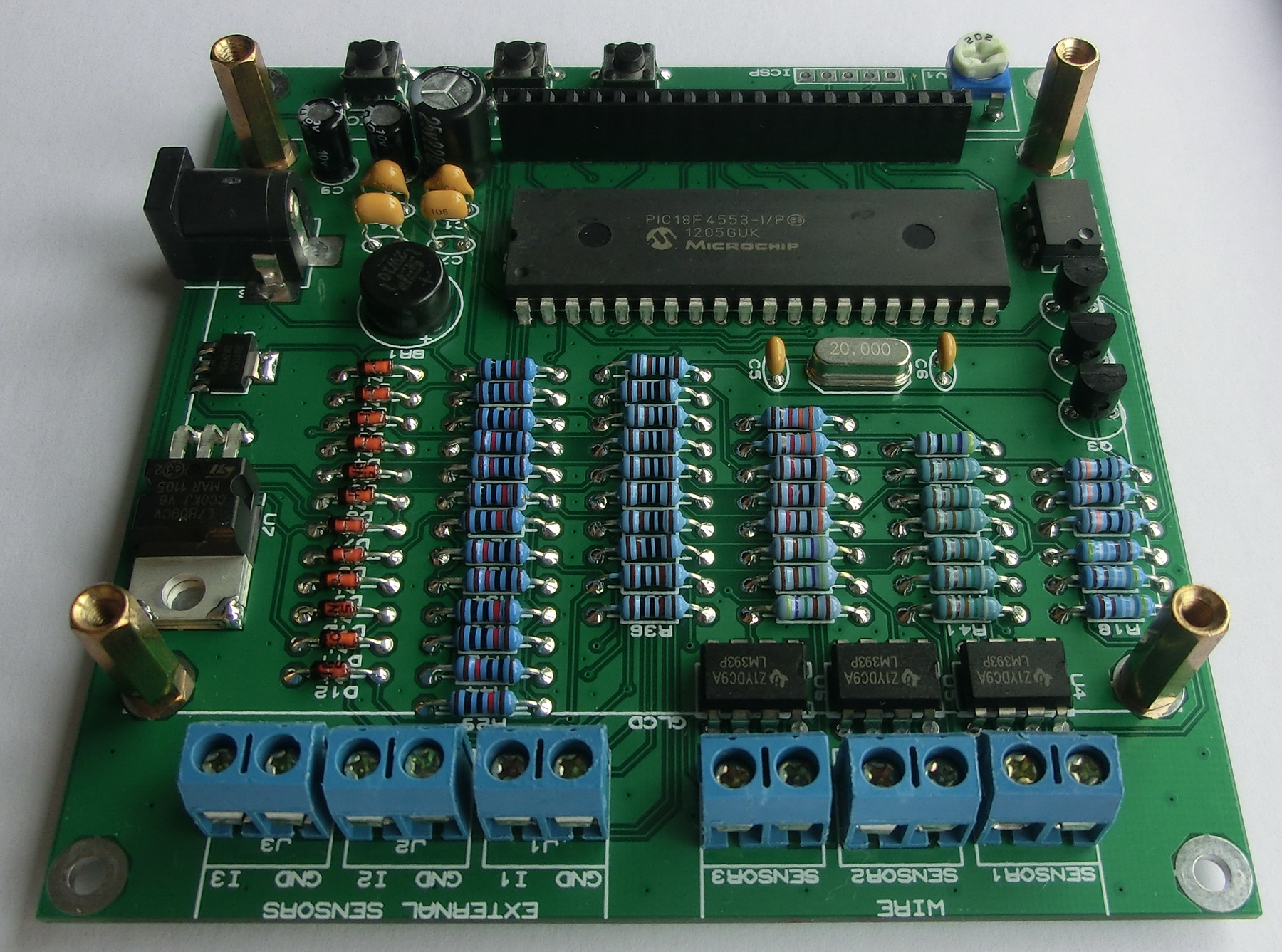
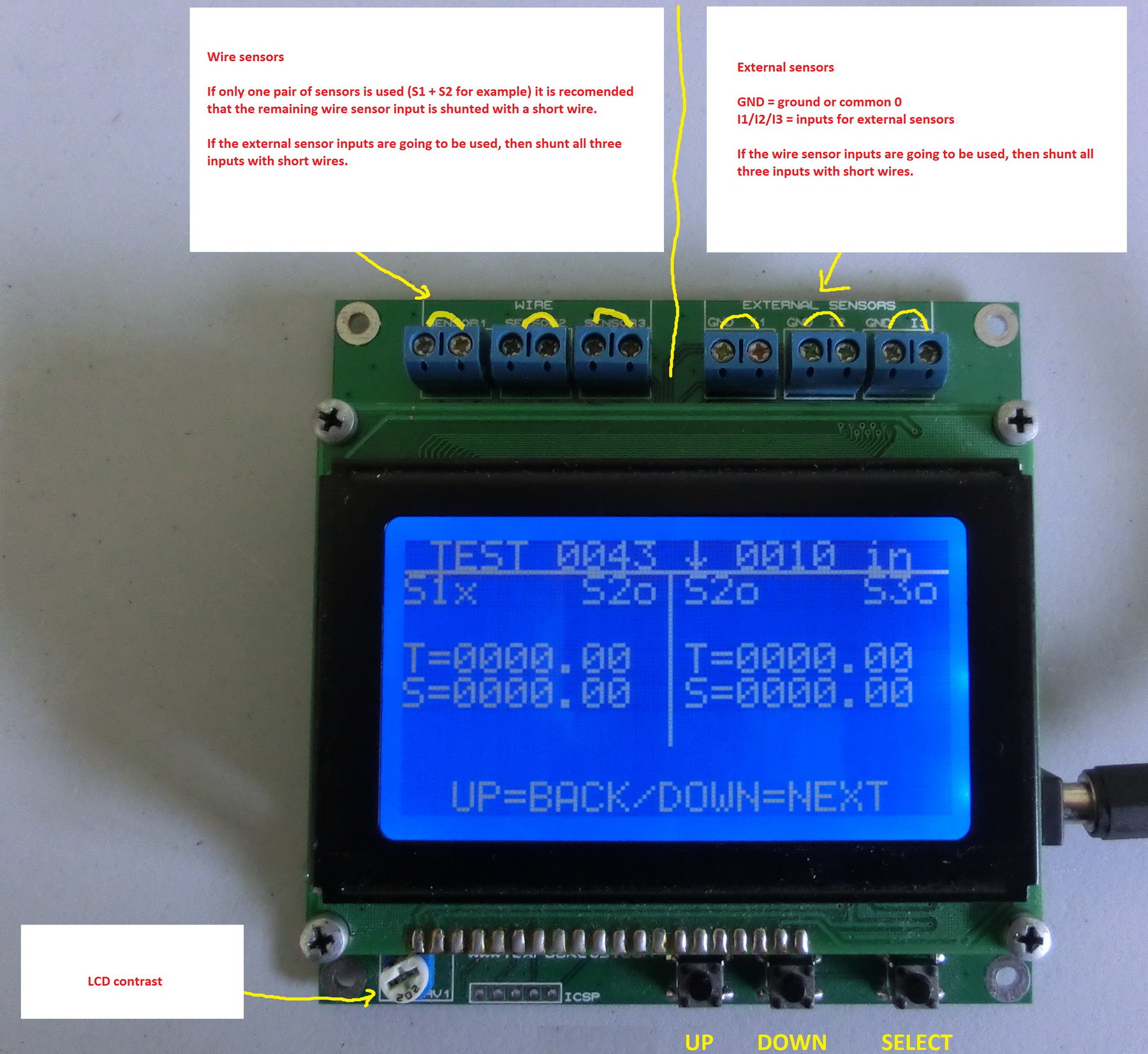
- 3 inputs for wire sensors
- 3 inputs for external sensors
- selectable triggering on rising or falling edge
- can calculate the speed based on the preset distance between the sensors
- possibility to measure acceleration or deceleration
- 6000 tests memory
- wires sensor integrity indicator
- minimum power supply of 11v AC/DC
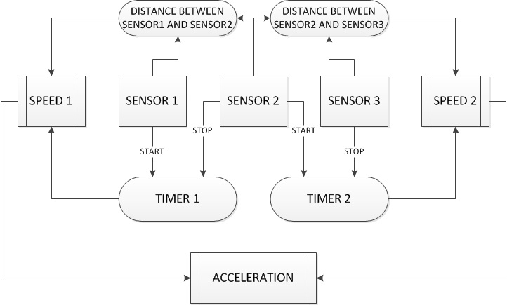
I am using two timers and the chronograph has three inputs, as depicted on the principal flow chart, which mean that Input1 trigger the start for timer1 and Input2 triggers the stop for timer1. In the same time Input2 will start timer2 and finally Input3 will stop timer2.
Based on the preselected distance and the detected time by the timer, the MCU will calculate and visualize the speed of the process and if you used three sensors then you can calculate the acceleration based on both speeds.
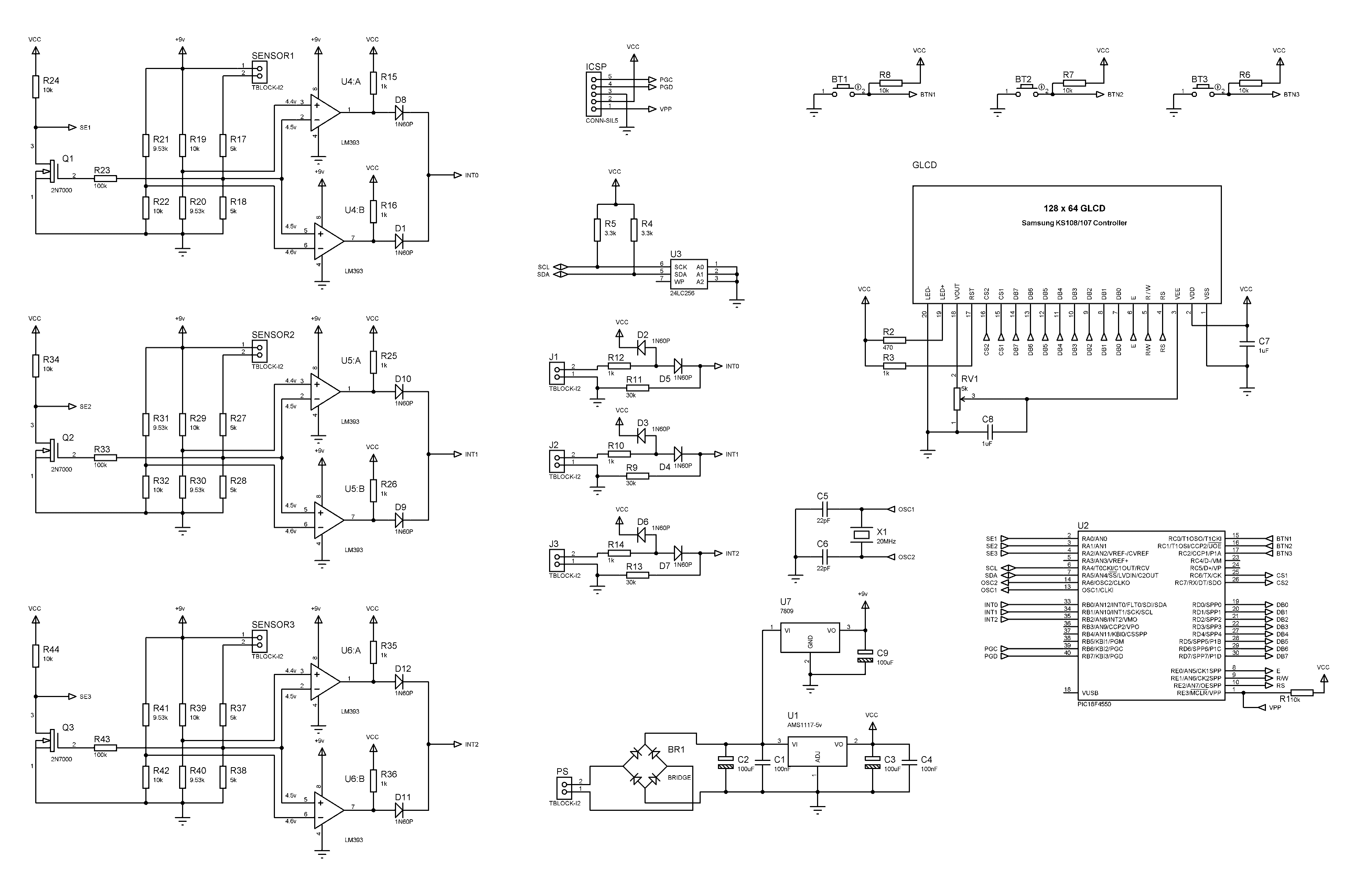
This chronograph is designed by using the PIC18F4550/PIC18F4553 internal timers while the internal logic is working at 48MHz. All three inputs are protected against under and overvoltage with clamping diodes. All inputs, wire and external sensors, are OR-ed with fast switching diodes.
Because this chronograph is capable of measuring very fast processes with resolution of only 100 nano-seconds, when using a wire as sensor you should select the wire as thin as possible because the speed at which the wire is being burned-through, stretched or simply destroyed, sometimes can be commensurable with the speed of the process you are measuring.
Also in some cases, depending on the measurement, the process can induce electric currents in the wire sensor, which can lead to wrong measurement results.
To mitigate those effects I implemented a simple window comparator with the double comparator IC LM393. The voltage at the wire is set to 4.5v through a two-resistor voltage divider. Then this voltage is compared to two window voltages of 4.4v and 4.6v, again set through two-resistor voltage dividers. Whenever the wire potential exceeds any of these two referent voltages, an impulse is generated and the start/stop condition is registered by the MCU.
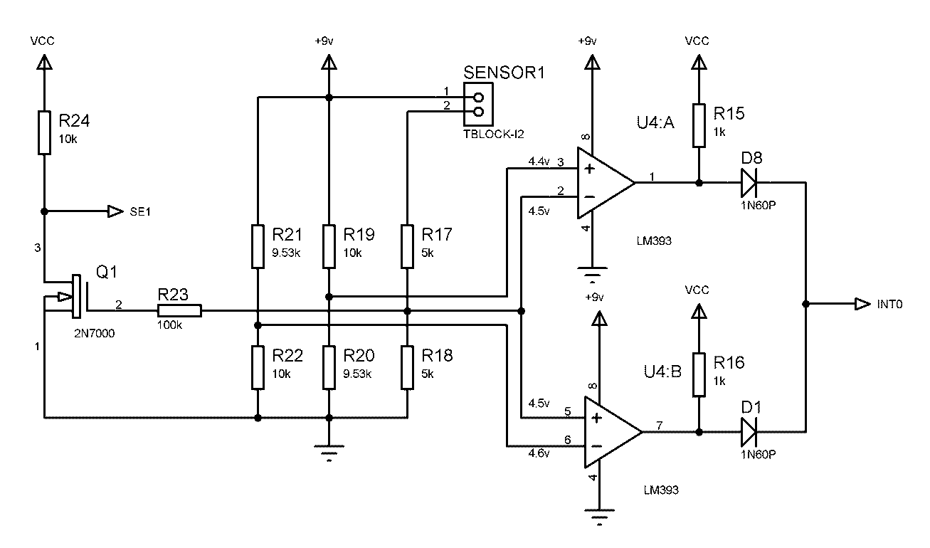
For all voltage dividers I used resistors with 1% tolerance. Precise measurements show that this approach is very effective in mitigating all previously mentioned effects.
The 2N7000 FET transistors acts as a simple switch that allows me to visualize on the LCD screen whether the wire sensor is properly connected or not.
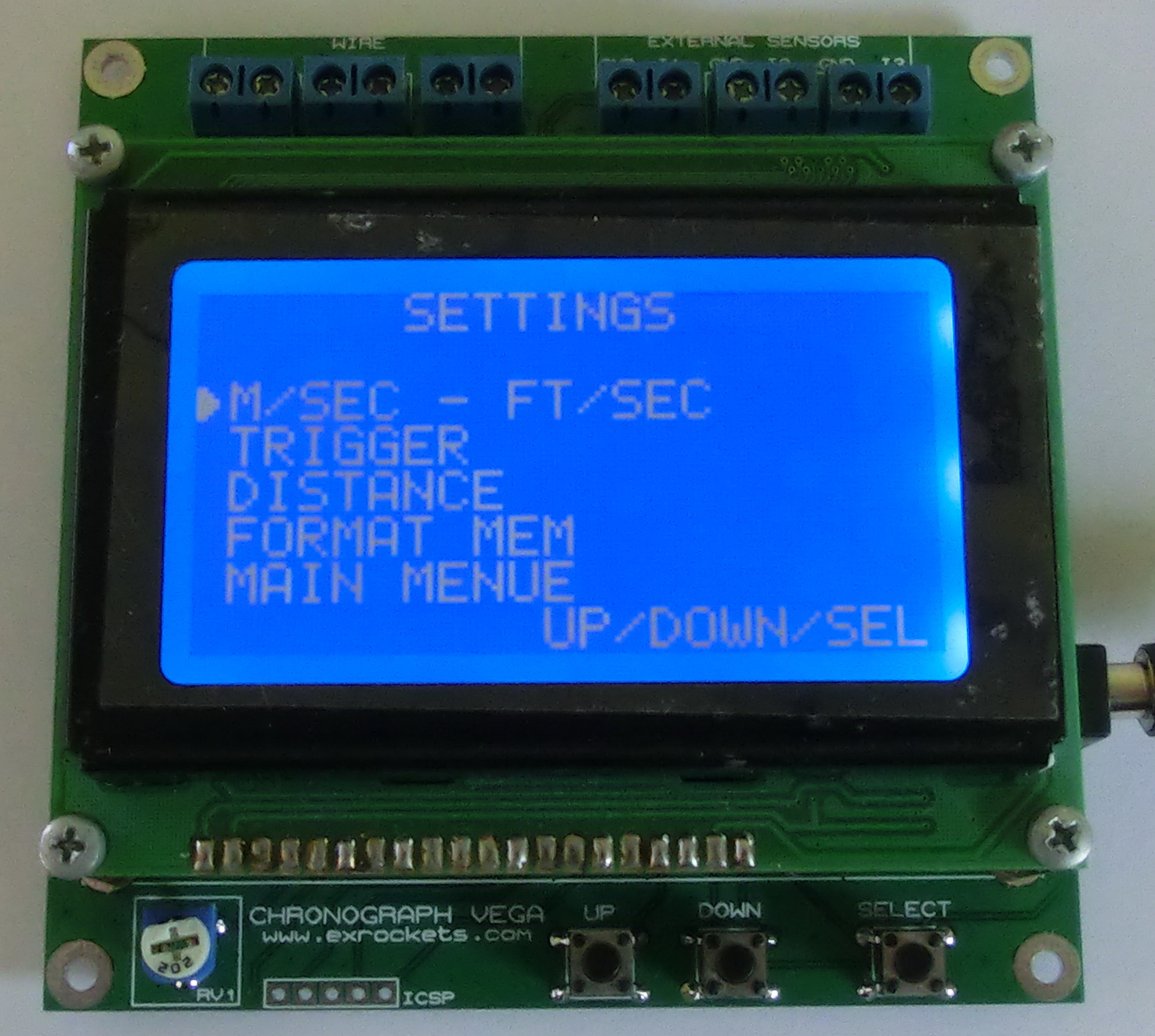
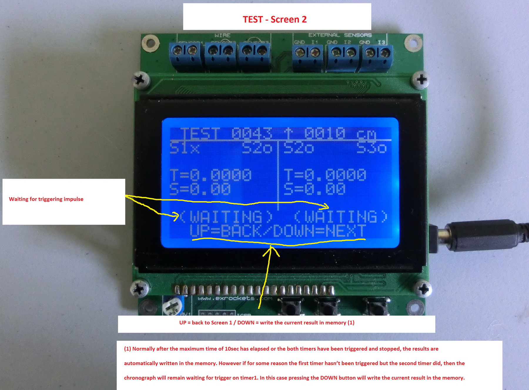
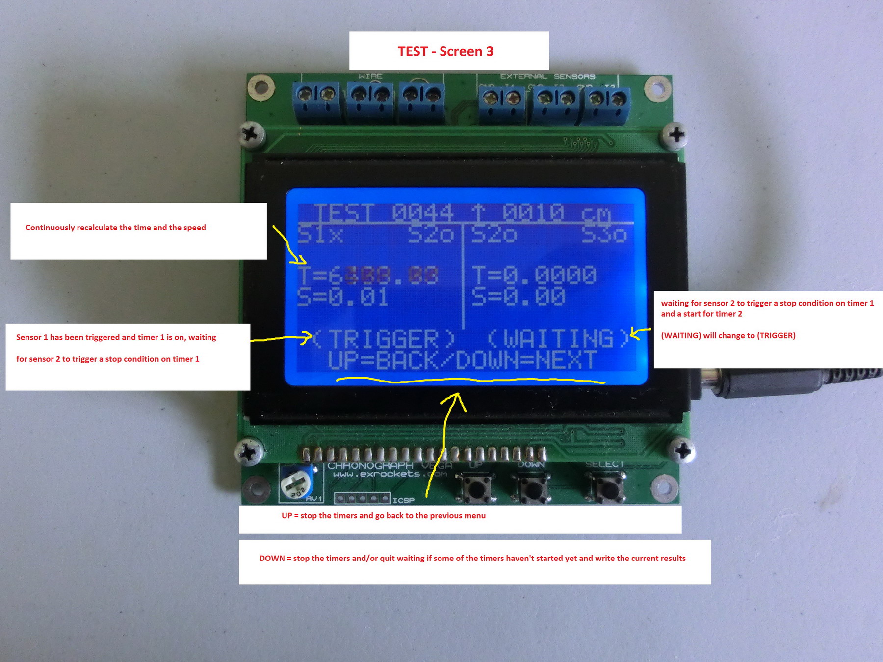
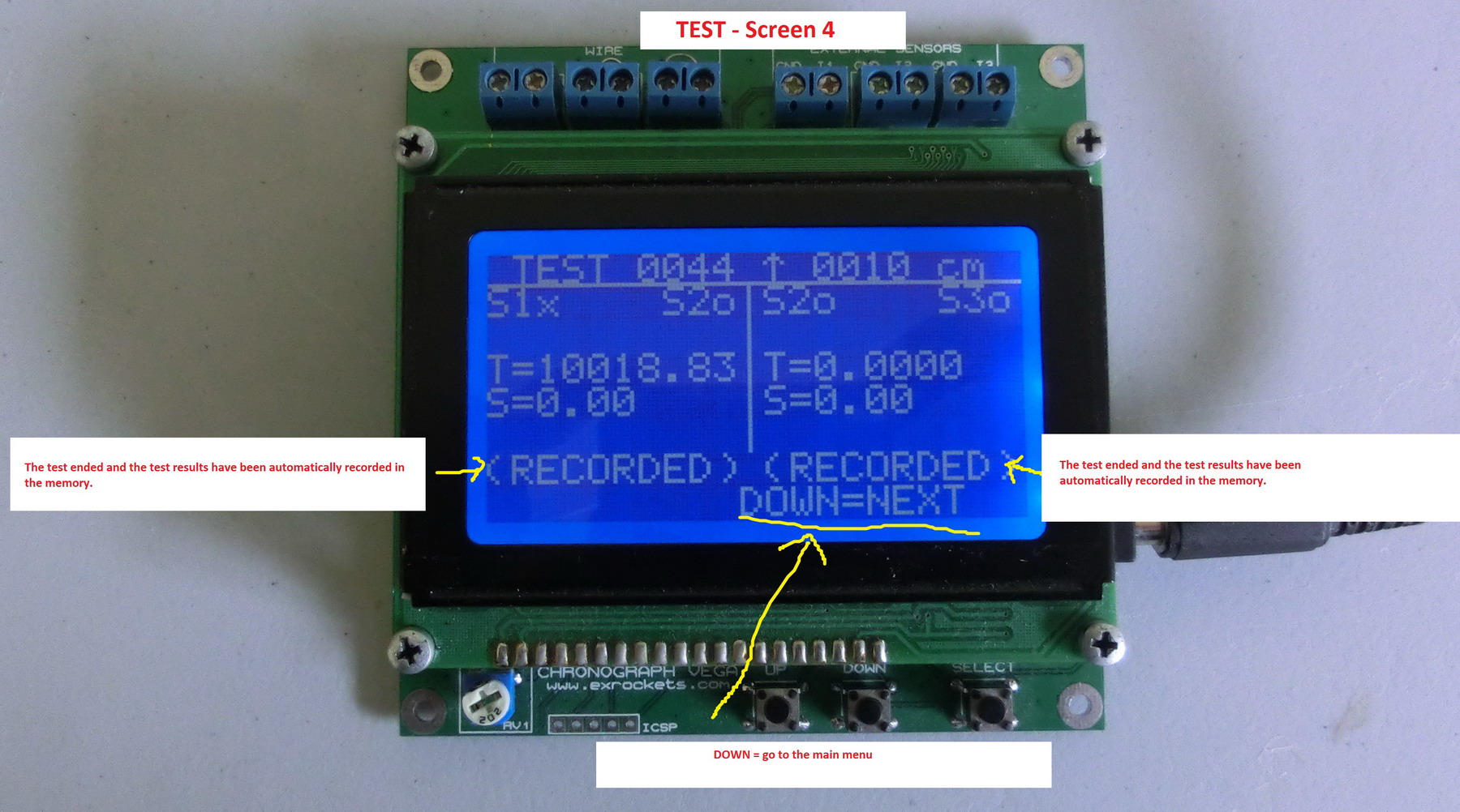
This chronograph is easy to use and setup, so instead I simply wrote the guide on few screenshots I have taken.
Pingback: LASER TRIGGER FOR CHRONOGRAPH - Electronics-Lab
please send mo more information if i use this for control time of pendulum clock
Best regards
Riccardo
Is there anyway you could port this code to a st7920 driver? Or provide the source?
Thank you
Nick
Pingback: LASER TRIGGER FOR CHRONOGRAPH • Tech Projects