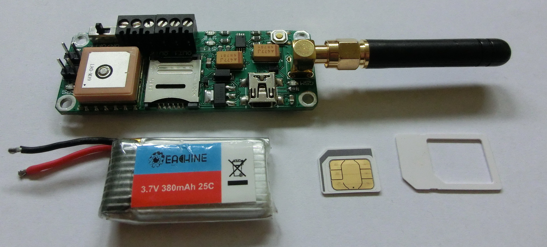
Based on my previous GPS-GSM tracker I also had a design for smaller tracker with mini SIM card and direct 3.7 Li-Po power supply that has been waiting for its turn to be assembled. This is the same tracker design as my previous tracker with the following differences:
– the power supply input is limited from 3.3v to 4.1v – i.e. a standard Li-Po battery
– memory is down to 512KB instead of 1MB
– SIM card holder is mini-SIM size
– schematic is a bit simplified
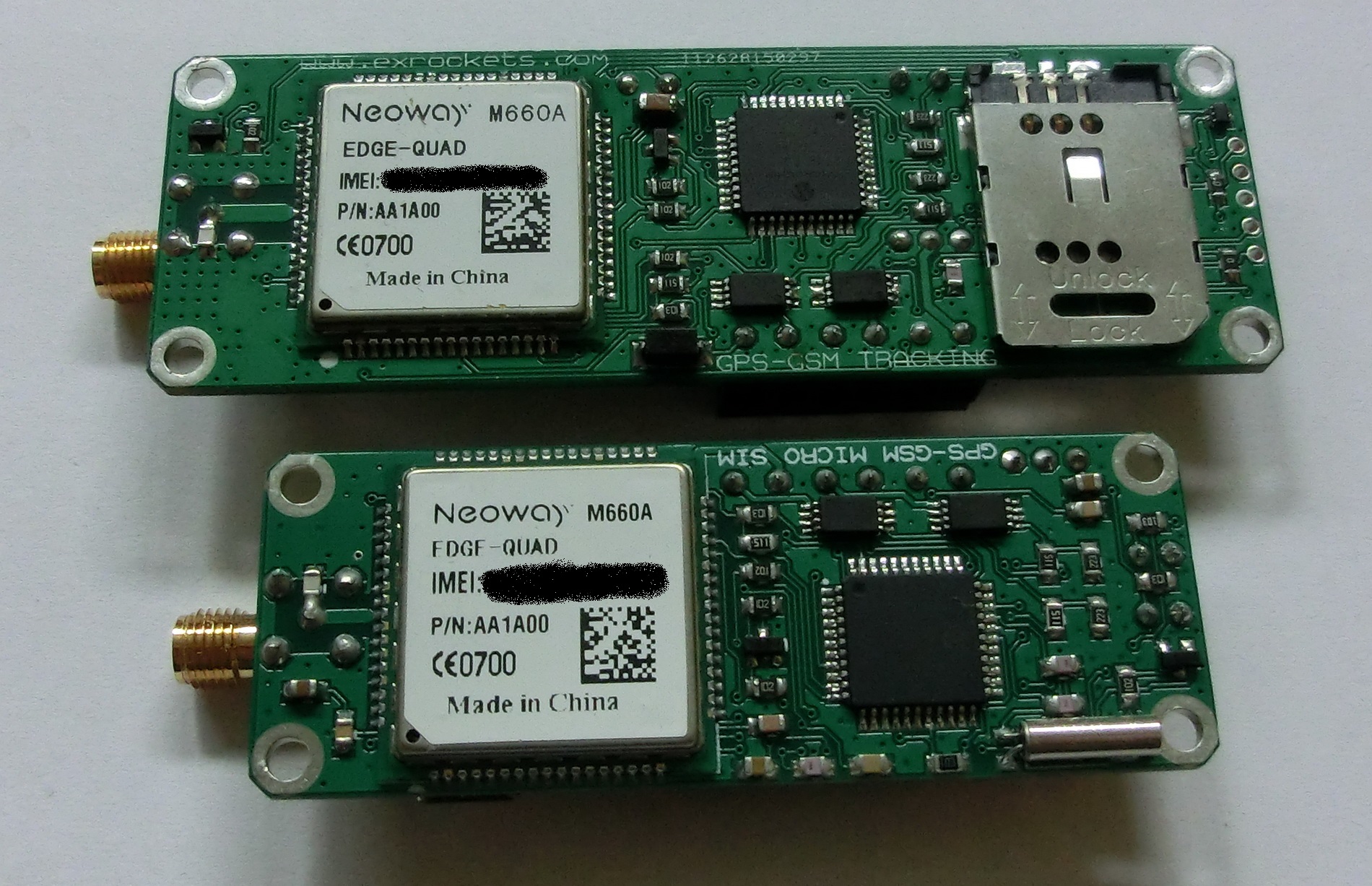
– size is 70x26mm instead of 90x30mm – you can see the difference in the next picture
The rest of the specifications remain the same:
– Quectel L80 GPS module
– Simcom SIM900 GSM module (or its analogue)
– 50mA nominal consumption
– 25mA consumption in economical mode
– 500mA peak current consumption when connecting to the network or receiving/sending messages
– two power MOSFET outputs capable of delivering up to 40Amp peak current
– two logical inputs with pull-up resistors
– USB port for PC communication
– test button
– 24gr weight
– total cost of the BOM ~25$
Functionally the tracker has the following capabilities:
– Switch on/off separately or together the outputs by sending SMS with text commands
– Sending periodic status messages
– Requesting a status message by sending SMS with text command
– Sending a status message at change on any of the logic inputs (if this function is enabled)
– Calculating the current distance and bearing from the start point i.e. 205m North-East
– Sending an automatic status message when a predetermined distance in any direction from the start point has been reached
Each message contains the following information: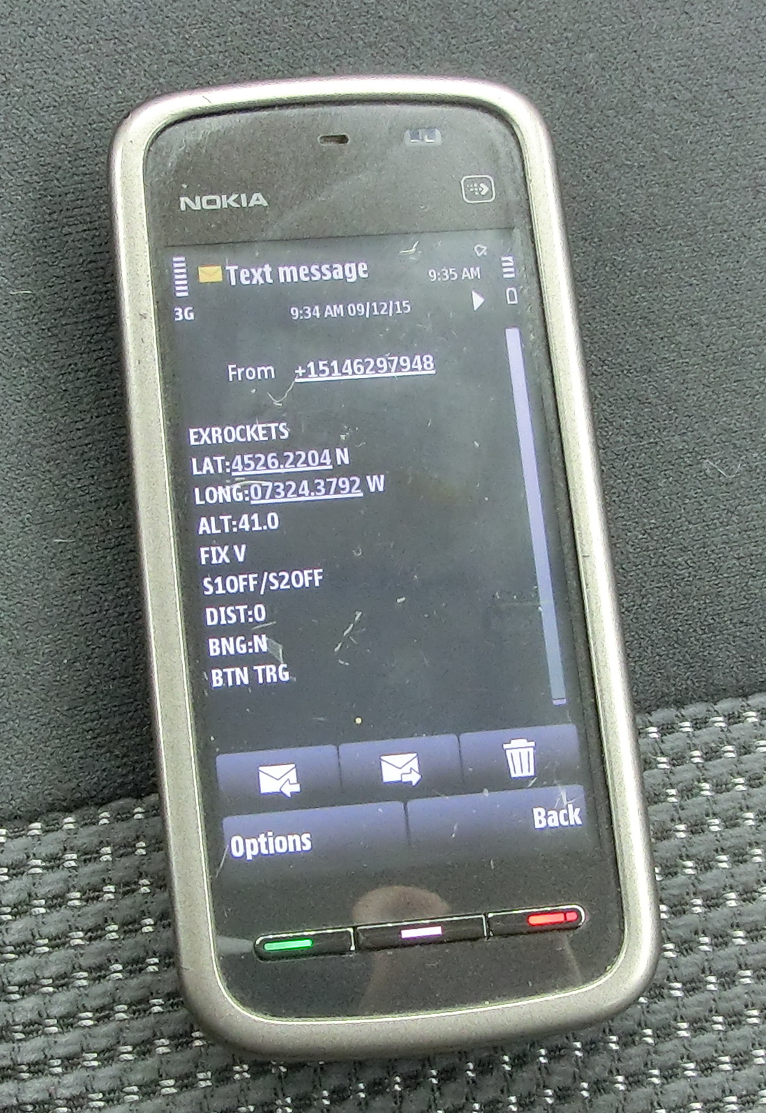
– Last valid Latitude
– Last valid Longitude
– Last valid altitude
– Current fix status i.e. valid or not valid
– Logic input S1 and logic input S2 status
– Distance from the starting point
– Bearing from destination point
– What triggered the message
The software has the following options:
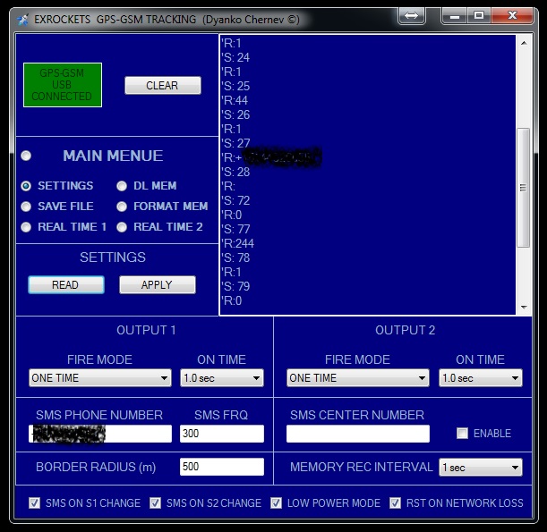
A: SETTINGS
– Each output can be separately set up when enabled by message to switch on only once, once every 15,30,60 and 120 seconds or continuously
– Each output can be set up how long to stay switched on – from 0.1sec to 5.0 seconds
– The SMS destination phone number
– How often the SMS messages to be send from 10 to 65000 seconds
– The SMS center phone number (not so often used nowadays, depends on the provider)
– Border radius in meters in any direction from the start point, which if crossed, an automatic status message will be send
– How often the current coordinates should be written in the memory (1sec to 65000 seconds). If the coordinates are written every second, then the memory is enough for about an hour
– Turn on/off the automatic messaging on change at any of the both logic inputs
– Turn on/off the energy saving mode. When enabled AND the SMS frequency is more than 45 seconds, the GSM module will be switched about 20sec before the SMS period and switched off right after the message was sent. This will save a considerable amount of energy, the drawback is that during the off period no SMS commands can be received. *Still crossing the border radius or change on S1 or S2 (if enabled) will force the module out of sleep and will send the status message.
– Turn on/off the reset on network loss function. If the network has been lost, the MCU will reset the GSM module. This is useful if fast switching between GSM networks is required or the network signal is weak and the module often drops. However if no other network is present then the module will keep restarting which draws considerable amount of energy.
B: Download the trip record from the memory
C: Saving the current information in the text box to a text file
D: Deleting the memory.
– There’s no real need to clear it before each trip as old data will be overwritten.
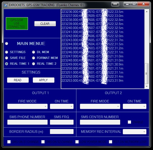
E: Real time 1
– The current GPS coordinates are decoded and transmitted in real time in short format i.e. Latitude, Longitude and Altitude only.
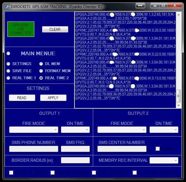
F: Real time 2
– The current GPS information is transferred in real time without any post processing i.e. all NMEA messages are shown.
The schematic itself is very straightforward and corresponds to the datasheets of the modules with the two remarks that I will explain further down.
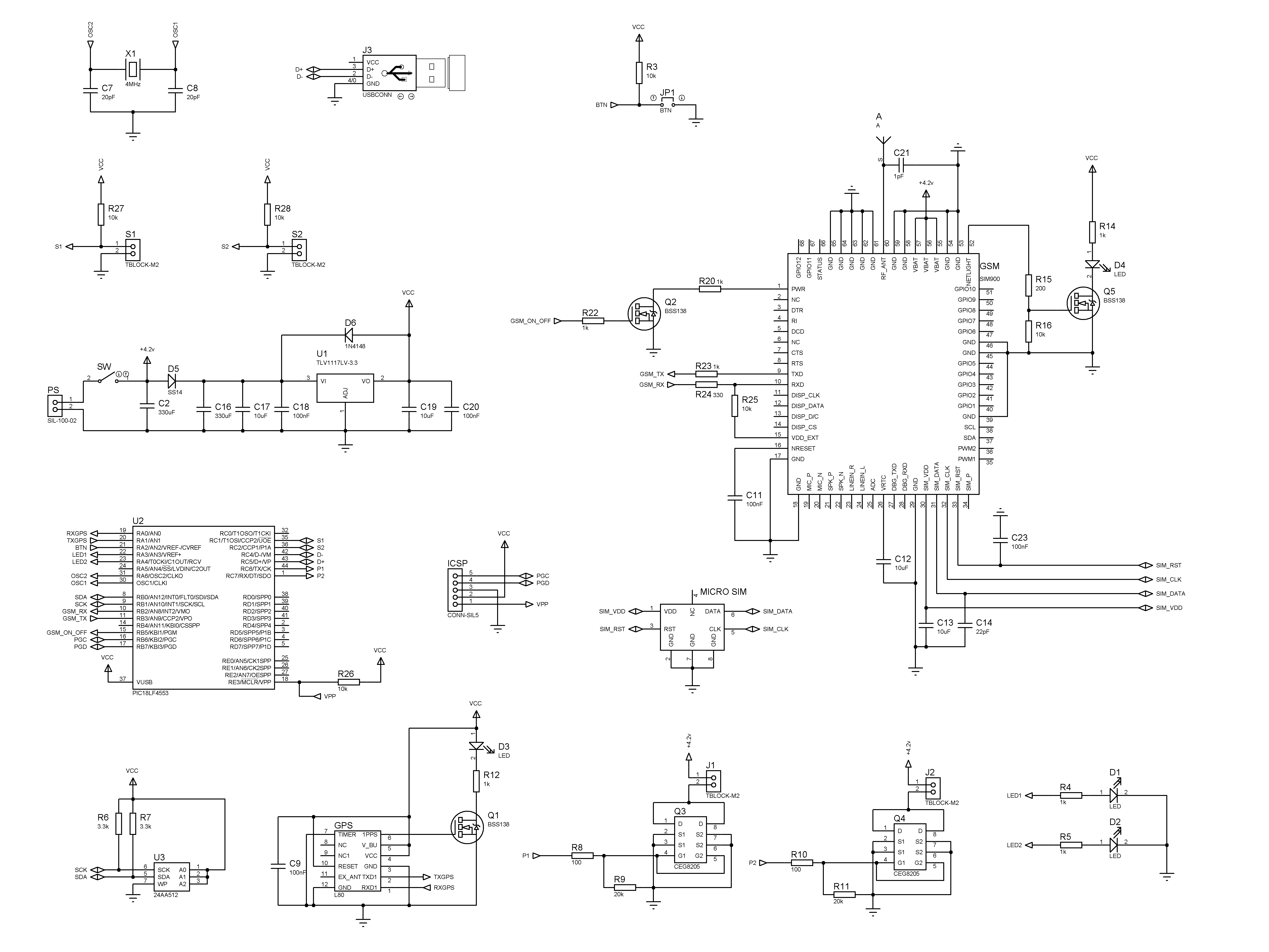
Input S1 and S2 usage:
Each logic input has pull-up resistor that allow it to be used as simple wire or breaker sensor. So one pin of the terminal block has low current 3.3 volts and the other pin is connected to ground. Hence if you connect a thin wire between the two pins on the terminal block and you break the wire this will change the logic state and message will be sent (if this option is enabled). Respectively if the connection between the two pins is open and you close it then this is again change in the logic state and message will be sent (if this option is enabled). This also can be used as a switch to receive impulses from external devises that will trigger SMS messages.
Output1 and Output2 usage:
Those are power outputs that are connected directly to the battery input and have MOSFET transistors acting as switches. When switched on they can conduct up to 40Amps current for short periods or 8Amps continuous current. Their usage can vary and it is up to the imagination of the constructor. Some examples are: firing the parachute, breaking the parachute robes if the wind is taking the rocket too far, igniting smoke signalization, giving periodic audio and visual signals, powering breaking the power to external circuits at will etc.
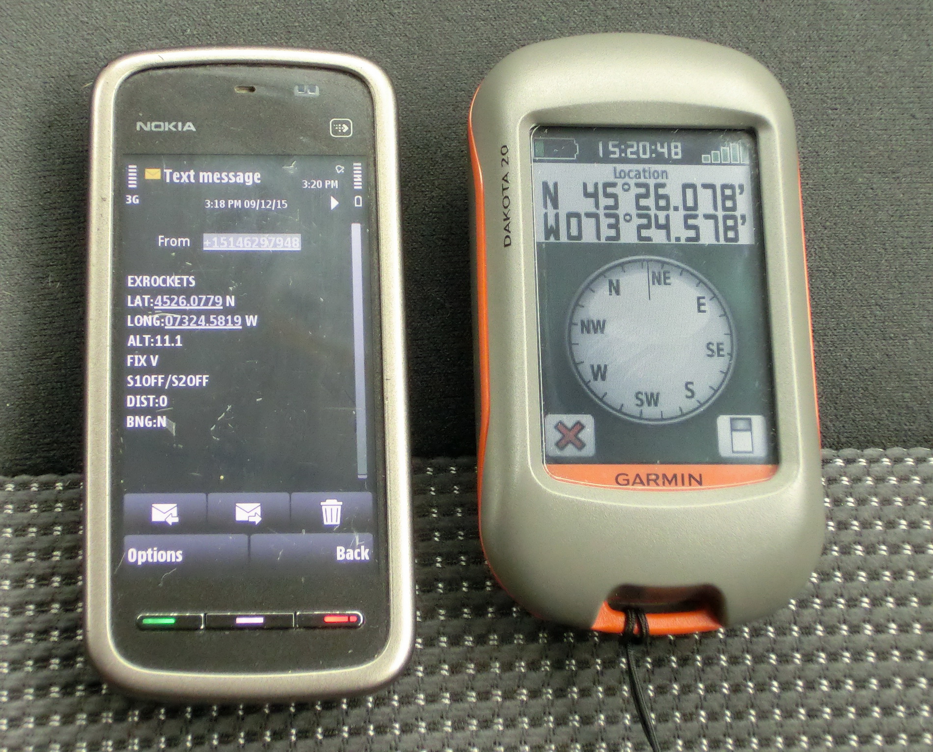
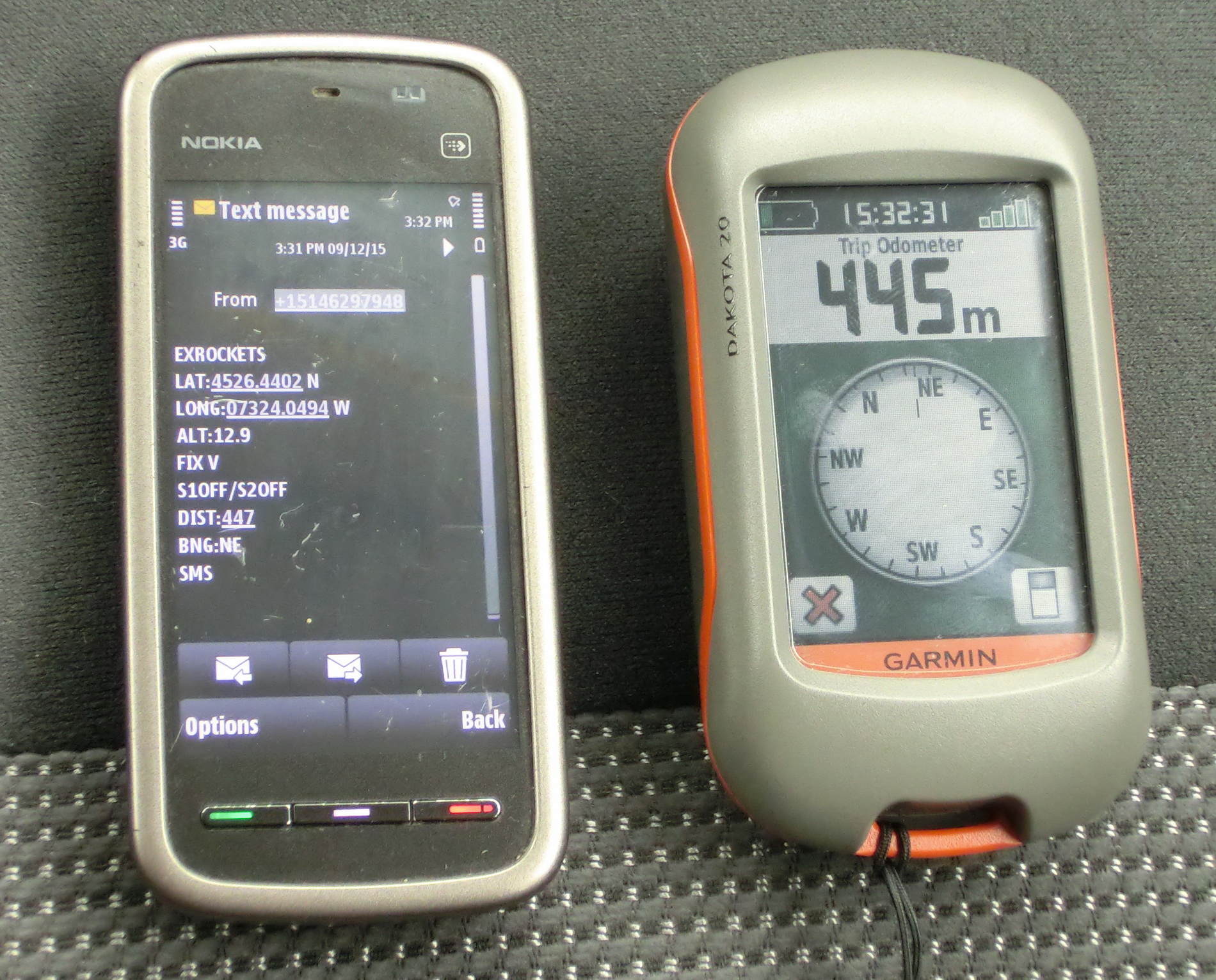
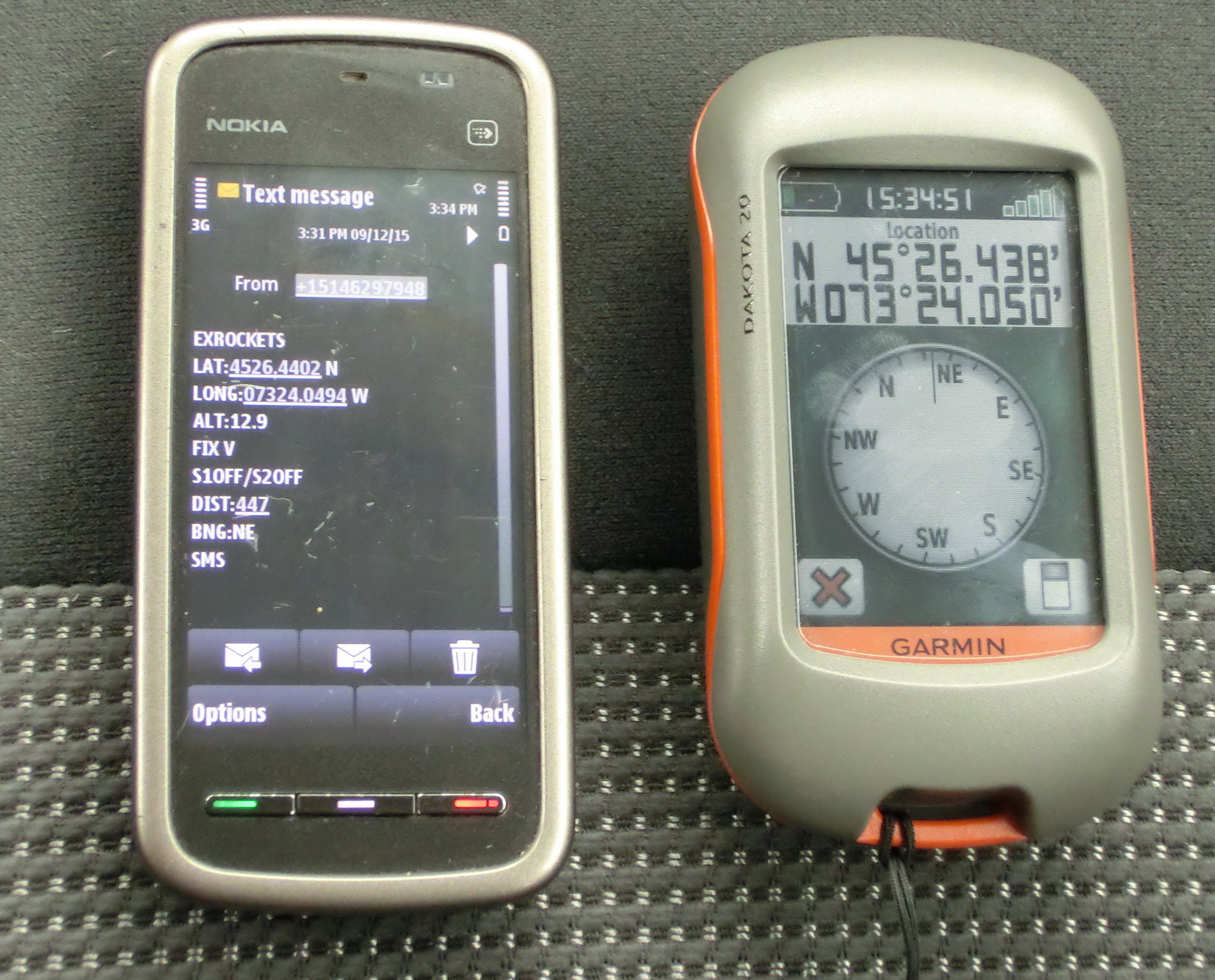
TEST FOR AUTOMATIC SMS AT BORDER RADIUS CROSSING –the radius was set to 300 meters, the pictures show the start and border position:
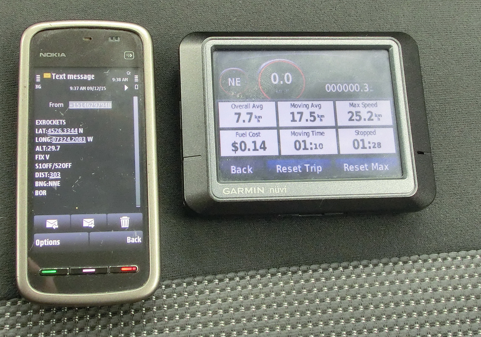
TEST FOR ACCURACY OF THE ALGORITHM FOR CALCULATING THE DISTANCE AND THE BEARING BASED ON THE GPS COORDINATES – the pictures show the start position, the current distance, bearing and coordinates.
VIDEO DEMONSTRATION OF HOW TO COMMAND THE OUTPUTS AND REQUEST STATUS MESSAGE THROUGH SMS
Finally I am attaching the PCB manufacturing files that can be used to order the printed circuit board, the board firmware that can be programmed with any PIC programmer and the PC software. The software program is the same as in my previous tracker and you can use it for the both trackers, however the firmware has some differences.
EDIT:
Recently bought new batch of the cheaper NEOWAY M660A modules. It looks like that in this version of the module firmware there is no auto-bauding function whereas the first NEOWAY M660A module that I received had this function implemented although nothing was mentioned about it in the datasheet. However the SIM900 module has the auto-bauding function described in the datasheet. So as a consequence after powering on both modules default to the initial 115200bps baud rate but, this version of the NEOWAY M660A can’t “automatically” switch to the lower 9600bps baud rate.
Simple solution was to write small subroutine in the firmware of my device that sends at 115200bps an instruction to the module to switch to lower baud rate. So if it happens that you have a NEOWAY M660A module and your device doesn’t send SMS you need to use the designated firmware that I uploaded (this firmware also works with the SIM900 since both modules accept the manual baud rate setup).
EXROCKETS_GPS_GSM_TRACKING APPLICATION
GPS_GSM TRACKING – HID.zip
GPS_GSM_MICRO_SIM – CADCAM.ZIP
The hole world is searching for good-price gsm sms module like this!
But I think there is no store to buy it, or?
We had 3 bikes and I like to set them up with this great device.
Greetings by Daniel
Hello Daniel,
this is not a commercial but a hobby project, so unfortunately I don’t sell these devices.
Regards
amigo, teria como manda o projeto ? estou querendo aprimora para a uma escola tecnica para alunos !
I am sorry but I don’t speak Portuguese.
very informative and insightful content