Note: The 10 Hz version is described here.
Update Note: As mentioned the SD card should be 2GB or less and formatted as FAT16. Due to addressing restrictions the SD card should contain only one partition, created as PRIMARY PARTITION with no unallocated space before the partition. Please note that some SD cards come with partitions, created as logical partitions and need to have their partitions recreated as mentioned previously.
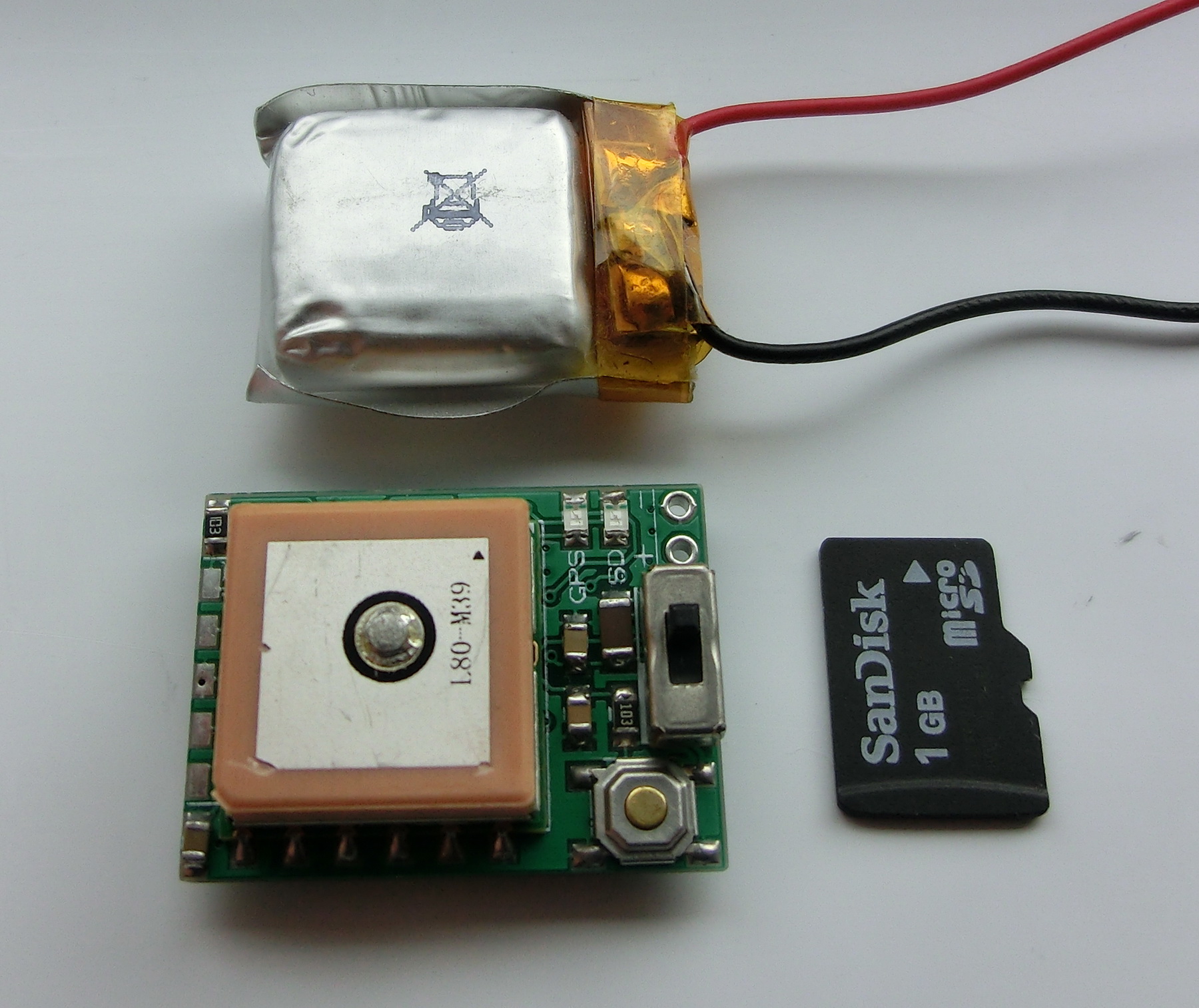
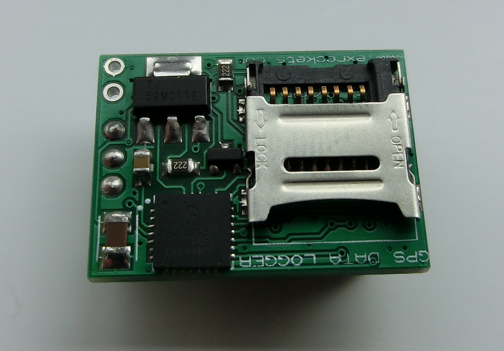
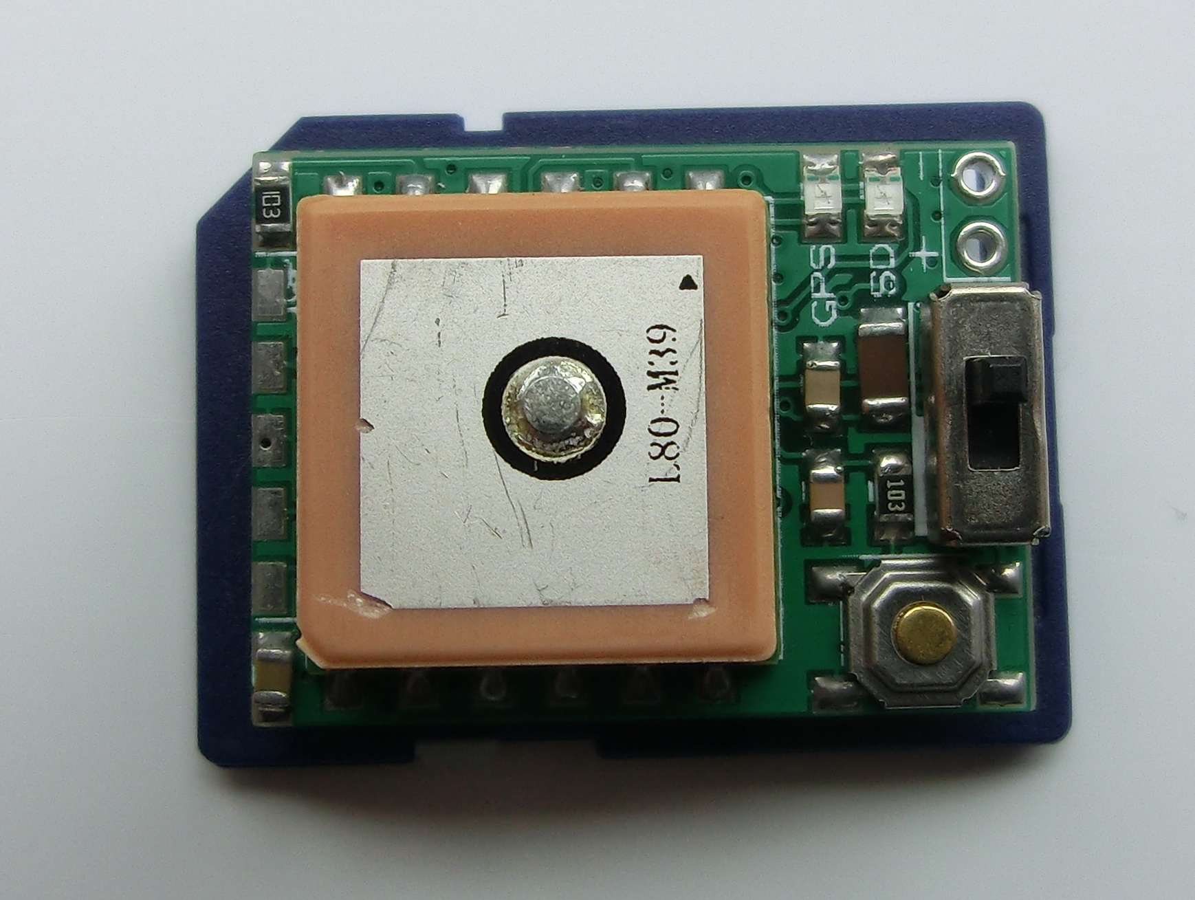 Based on my first GPS data logger I made a new version which is even smaller than the initial design and should be able to fit in any rocket, RC model etc. The new GPS data logger uses micro-SD card and 3.7v LIPO battery as power source. The board was also optimized and the new size is 20mm x 27mm – less than a standard SD card as you can see on the picture to the right.
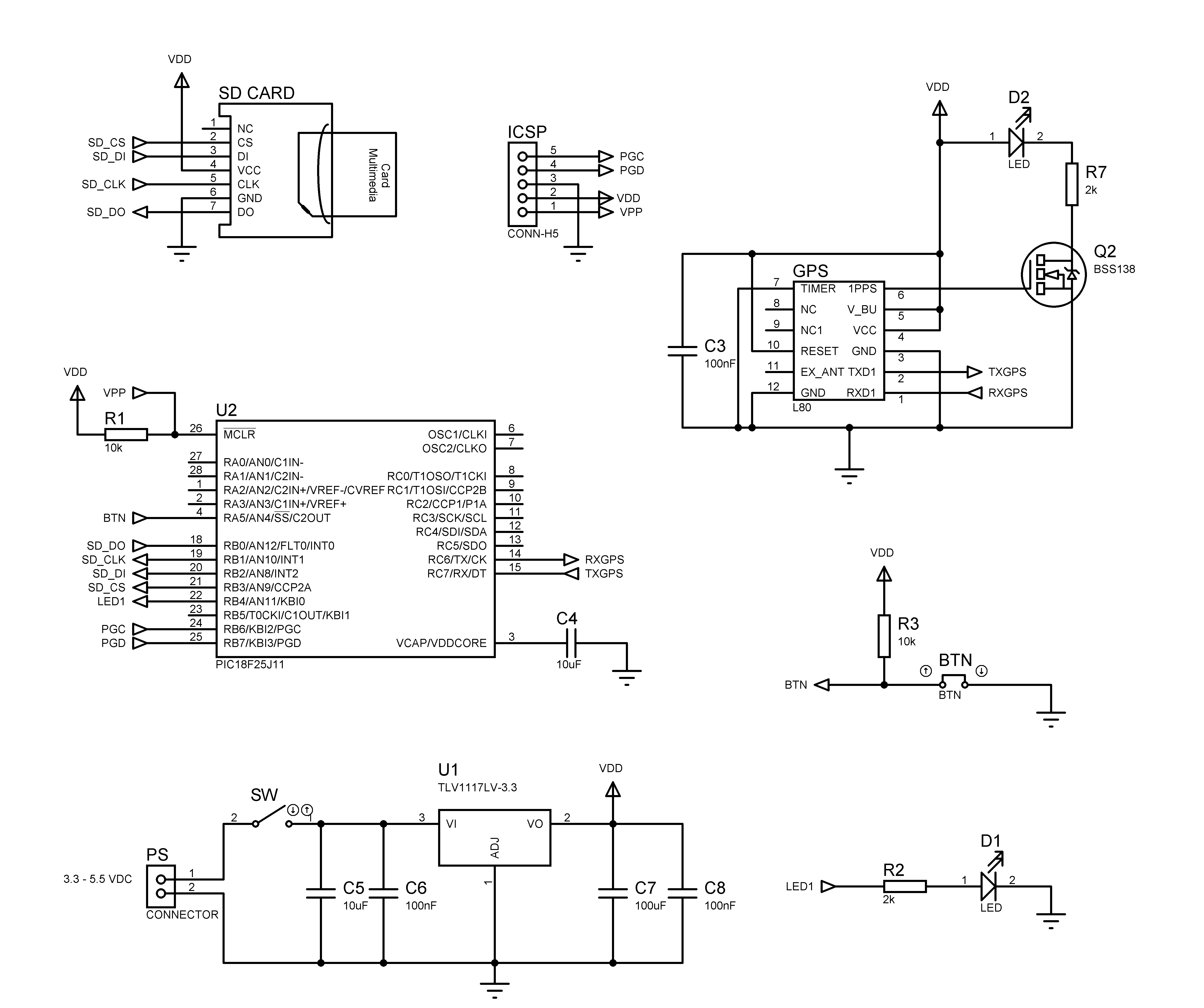
The design is based on my first GPS data logger – microSD card, GPS module, LDO power supply and PIC18F25J11 micro controller – all parts are easily obtainable from on-line sources like Ebay or Aliexpress. However some of the pins were changed and the switch transistor for the SD card power supply was removed.
Using the GPS data logger is also quite simple:
– Connect to at least 3.3v power supply, the maximum is 5.5 volts.
– Place the SD card with SETTINGS.TXT file on it in the socket
– Switch the GPS logger on
– Wait until the SD card is initialized and all data files are created – thus wait until the SD card LED stops blinking
– If the SD LED remains solid on, then there’s something wrong with settings file or the SD card – for the exact reason please check the LOG_x.TXT file on the card (the file structure is explained further down)
– Wait until the GPS LED start blinking, indicating that the GPS signal is found and correctly decoded
– Press and hold for 1 second the SMD button to start the GPS data logging
– The NMEA GPS data stream will be decoded and recorded in the corresponding text data files (the file structure is explained further down)
– Stop the GPS data logging press and hold the button again and wait until all files are closed, hence until the SD LED remains solid off
* To safely remove the SD card you need first to stop the data logging and make sure that the SD LED is off when you remove the card
** The power consumption is the sum of the SD card power consumption, the GPS module and the data logger power consumption. If the sampling time is 10sec or less, then the data logger and the GPS module power supply will be always on. The SD cards can draw between 2mA and 100mA depending on the manufacturer and the model. The data logger’s own consumption is 8mA and the GPS uses about 30mA when fully powered. If the sampling time is more than 10sec, then depending on the sampling rate, different power schemes will be used and some parts will be switched off to conserve energy between each data point record.
FILE SYSTEM:
SETTINGS
Write the sampling time in the first line. The sampling time is expressed in seconds. The minimum sampling time is 2s and the maximum is 99999999s. Make sure that there is a semicolon after the sampling time. After the sampling time, write the number of points to be taken. 0 means no point limit. The minimum point number is 1 and the maximum is 99999999. Make sure that there is a semicolon at the end.
SETTINGS.TXT – this file contains the sampling rate and the number of data points to be recorded. This file has to be present on the SD card for the proper function of the GPS Logger
LOG FILES
In total 7 files are created for each new GPS data logging. The name of each file indicates what information it will contain and “x” for the serial number of the record (not an absolute serial number but relative to the current number of files on the card)
LOG_x.TXT – contains the data logger system and status information
GGA_x.TXT – contains the $GPGGA message (Fix information)
GSA_x.TXT – contains the $GPGSA message (Overall Satellite data)
GSV_x.TXT – contains the $GPGSV message (Detailed Satellite data)
RMC_x.TXT –contains the $GPRMC message (Recommended minimum data for GPS)
VTG_x.TXT – contains the $GPVTG message (Vector track an Speed over the Ground)
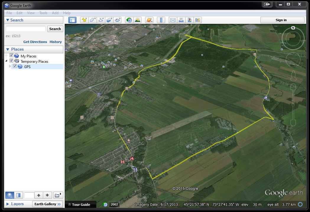
GPS_x.KML – this file has all data points converted from DDDMM.MMM to DDD.DDDDDDDD and it is in the format used by Google Earth and Google Maps to display a path in 3D over the ground. To use this file, simply load it in Google Earth.
The PCB manufacturing files and the MCU firmware can be downloaded from here:
GPS_DATA_LOGGER – CADCAM.ZIP
GPS_DATA_LOGGER – FIRMWARE 1.3.ZIP
Hello. I sent you an email about a week ago about buying one of these. I don’t know if you missed it so I’ll try here. Please check you mail.
Sincerely
Philip
I would buy one of these too if you made a batch.
Sorry, I don’t have any spare.
Hi,
I’m wondering if you’ve considered designing something like this that is Arduino Compatibly (like a pro mini) and with a more modern GPS module to increase its sample rate?
Very impressive.
Hello Dan,
actually this module is quite good and can output up to 10 Hz, I simply did not use it at more than 1 Hz. However I have plans for making a more compact version of this project which will be working at 10Hz and it will be used mostly for small RC model cars and airplanes – unfortunately I’m quite short of free time.
Regarding the Arduino – I prefer using PIC’s since I already have written my libraries for them and there is a wider choice of PIC micro-controllers.
Best wishes.
Dear pinko,
Thank you for this project. We are very interested by your last comment : compact and 10Hz rate, for our very small rc boats ! (less than 30cm and more than 100 km/h).
With fun with you !
Hervé
Hello Herve,
the new 10 Hz GPS data logger might be interesting for you, I posted full description in the new blog entry:
http://www.blog.exrockets.com/blog/high-speed-10-hz-mini-gps-data-logger-with-micro-sd-for-rc-models-and-model-rockets/
Best wishes.
Hello,
do you happen to have a complete Bill of Material for this PCB? The schematic doesn’t have complete part numbers.
I’m looking to build a few. in case anyone is interested as well please contact me.
Hello Hooman,
I placed a link to the BoM at the bottom of the page. Tolerances of the passive components don’t matter. The rest was purchased from E-bay and Aliexpress.
Regards
Thanks!
getting the board assembled now. can you walk me through the firmware programming?
Hi Hooman,
I am using PICkit 3 In-Circuit Debugger from Microchip. Normally I solder a 5p 2.54mm pin header to the ICSP port for better connection, flash the firmware and remove the header.
did exactly that… worked like a charm!
now the board powers up, the red LED come on, but no GPS LED, and after a while the red LED starts blinking… nothing is written on the SD Card.
can you tell me what i’m missing?
thanks for all your help
The GPS LED starts blinking once it had acquired a valid satellite fix.
The SD card should be less than 2GB and formatted as FAT16. Also the SETTINGS.TXT file (you can download it from the description) should be present.
Data logging doesn’t start automatically – to start and stop it you have to press the button.
got the 1GB SD, copied the settings file onto FAT16 formatted SD Card. The SD Card LED keeps on flashing (is that normal)? its never solid to begin with. Also do you know roughly how long i should wait for a GPS signal (So until the GPS LED begins flashing)?
The GPS time to first fix is about 5 minutes if more than few days passed since the last fix or you moved more than 200km. Otherwise it is about 1-2 minutes.
For the SD card – flashing fast means that there is a problem with the card. Make sure the “SETTINGS.TXT” is with capital letters, also check you solder joints that they are making good contact if you have re-solder them. Finally try another SD card – I’ve seen cheap E-bay SD cards for some reason drawing too much current on the SPI port.
where can I get this (Germany), is not Aliexpress or ebay available
Capacitors 1 C7 100uF 1206
1 U1 TLV1117LV-3.3 SOT223-3
1 U2 PIC18F25J11 QFN
1 ICSP CONN-H5
1 PS CONNECTOR
try http://www.digikey.com
The most of them is also not avaible there. And it is in USA not in Germany.
Any other Idea`s?
which parts are you looking for? and digikey does ship to europe as far as i know.
Hello Peseta3,
100uF 1206 SMD capacitors, TLV1117LV-3.3 and PIC18F25J11 28-QFN are being sold in e-bay, I just checked. You can find them at Conrad as well.
The ICSP is simply pads on the PCB used for flashing the firmware and the PS connector is the power supply connector, which is also directly printed on the PCB.
ok thank you I try it again.
hmm I only found “100nf” not “uf”
and not LV3.3 only other maybee LV25 or so
and what about the PIC18F25J11 28-QFN is it complete change with PIC 16F18326 ?
Hmm , I see that I have to upload the firmware on the Pic´s.
How can I do this?
Is it complicate for an Newbee?
Hi,
Normally it is not but if you don’t have any experience flashing PIC’s, this will be a difficult task.Besides you will need a PIC programming device.
Witch PIC programming Device do you recommend?
I am using PICKIT3.