Update Note: As mentioned the SD card should be 2GB or less and formatted as FAT16. Due to addressing restrictions the SD card should contain only one partition, created as PRIMARY PARTITION with no unallocated space before the partition. Please note that some SD cards come with partitions, created as logical partitions and need to have their partitions recreated as mentioned previously.
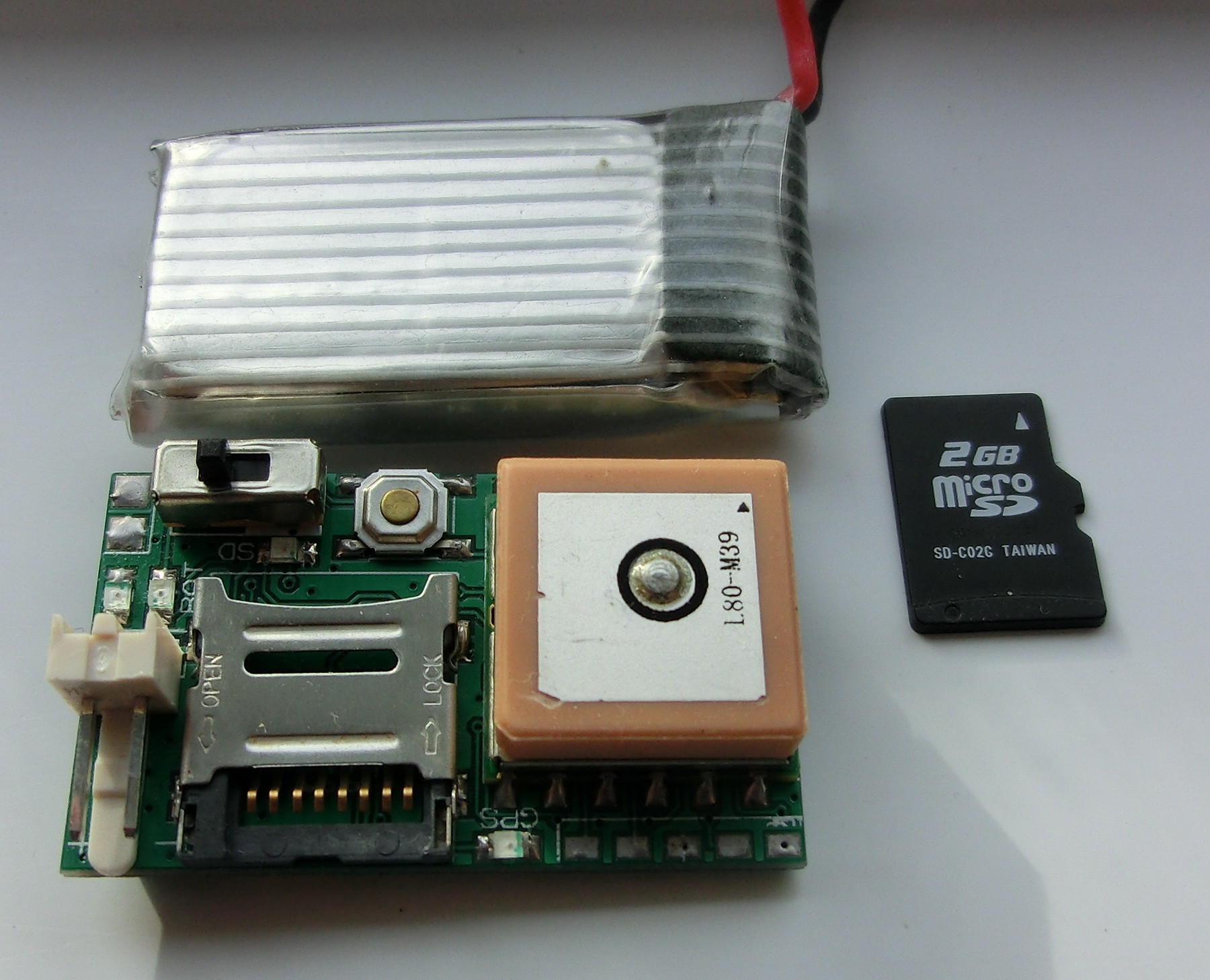
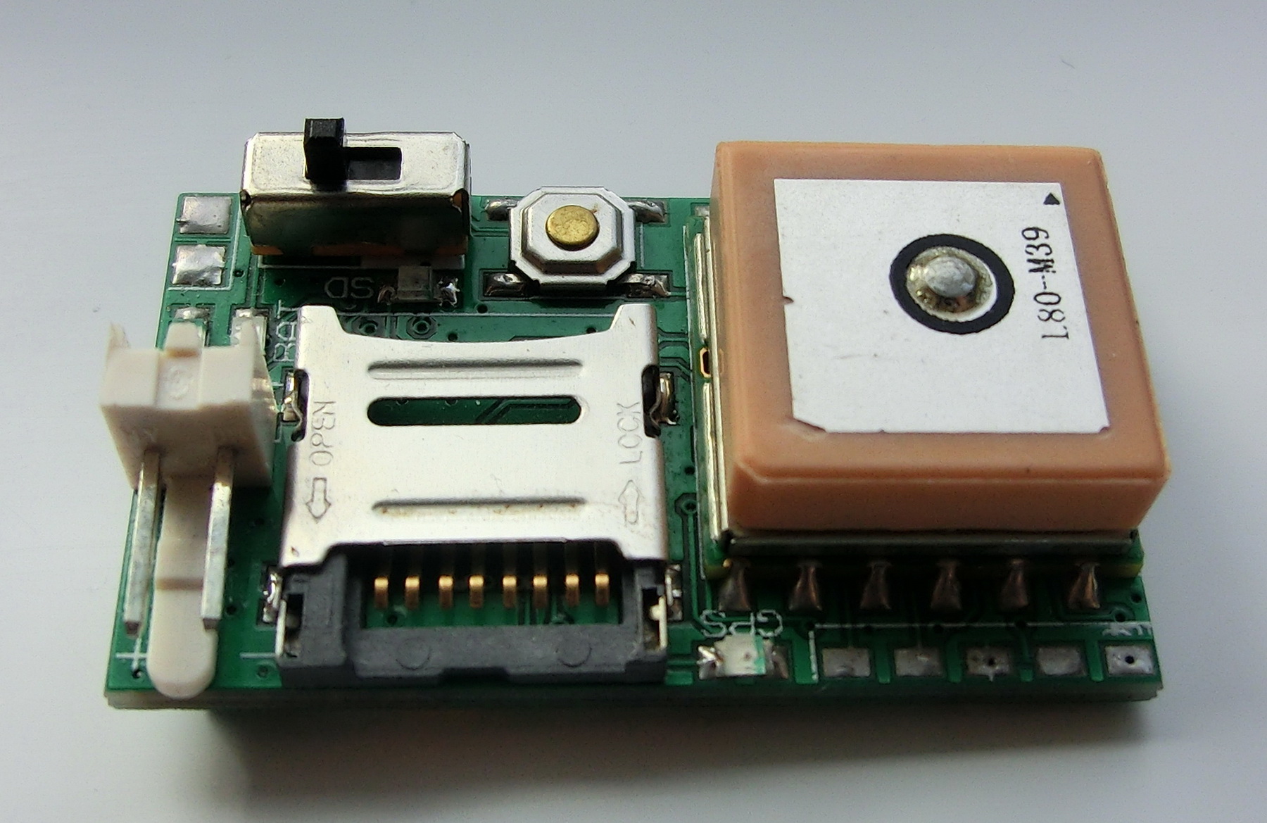
The only difference between the current GPS data logger and the MINI GPS DATA LOGGER is that the current modification has a built in charging circuit for the LIPO battery. This is very convenient because you don’t have to take off the battery every time when you need to charge it. However the additional circuit required about 10mm additional board space and the size is 22mm x 37mm – still the GPS data logger is with the size of a standard SD card and should be able to fit in any rocket, RC model etc. The new GPS data logger uses micro-SD card and 3.7v LIPO battery as power source.
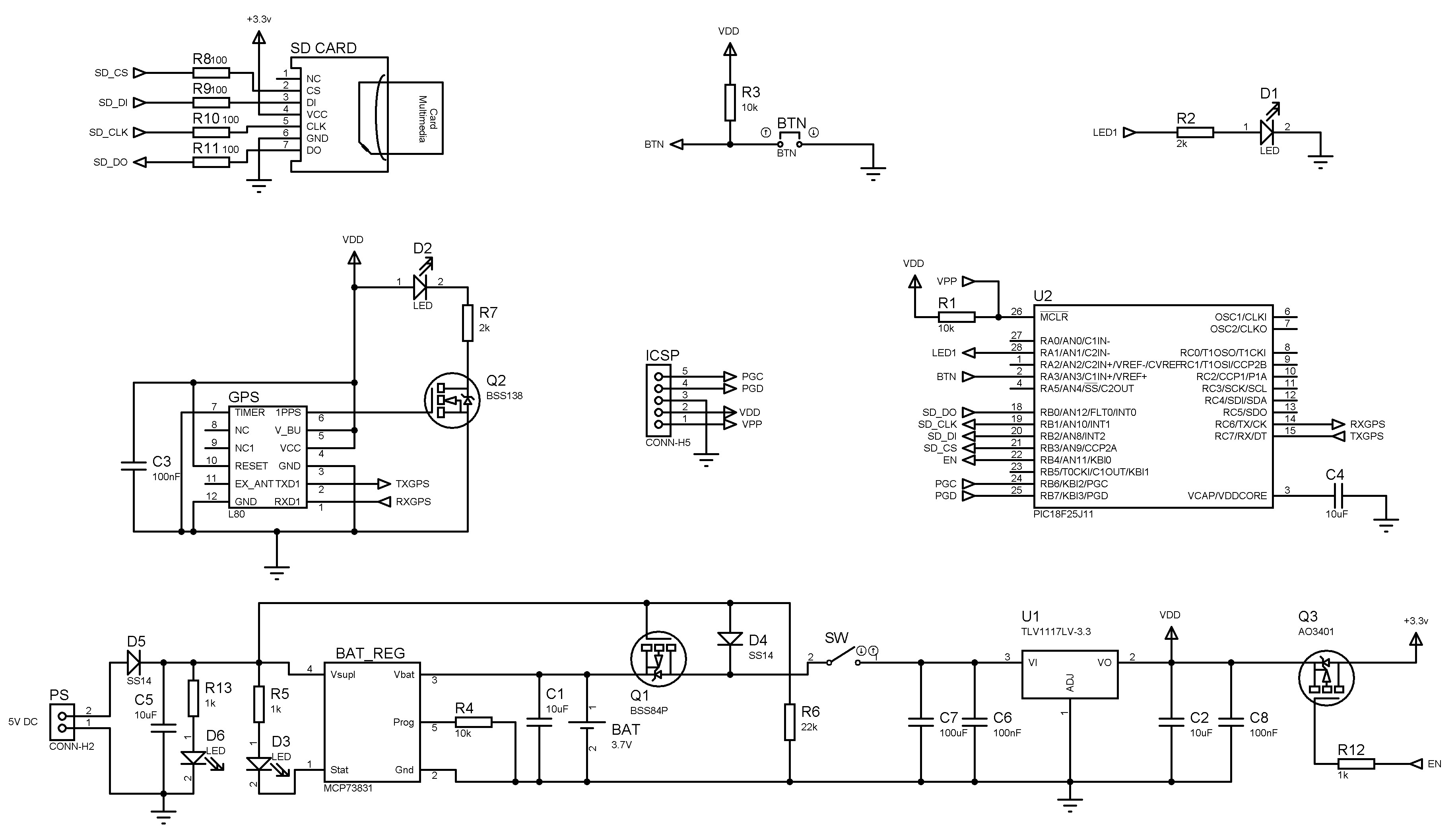
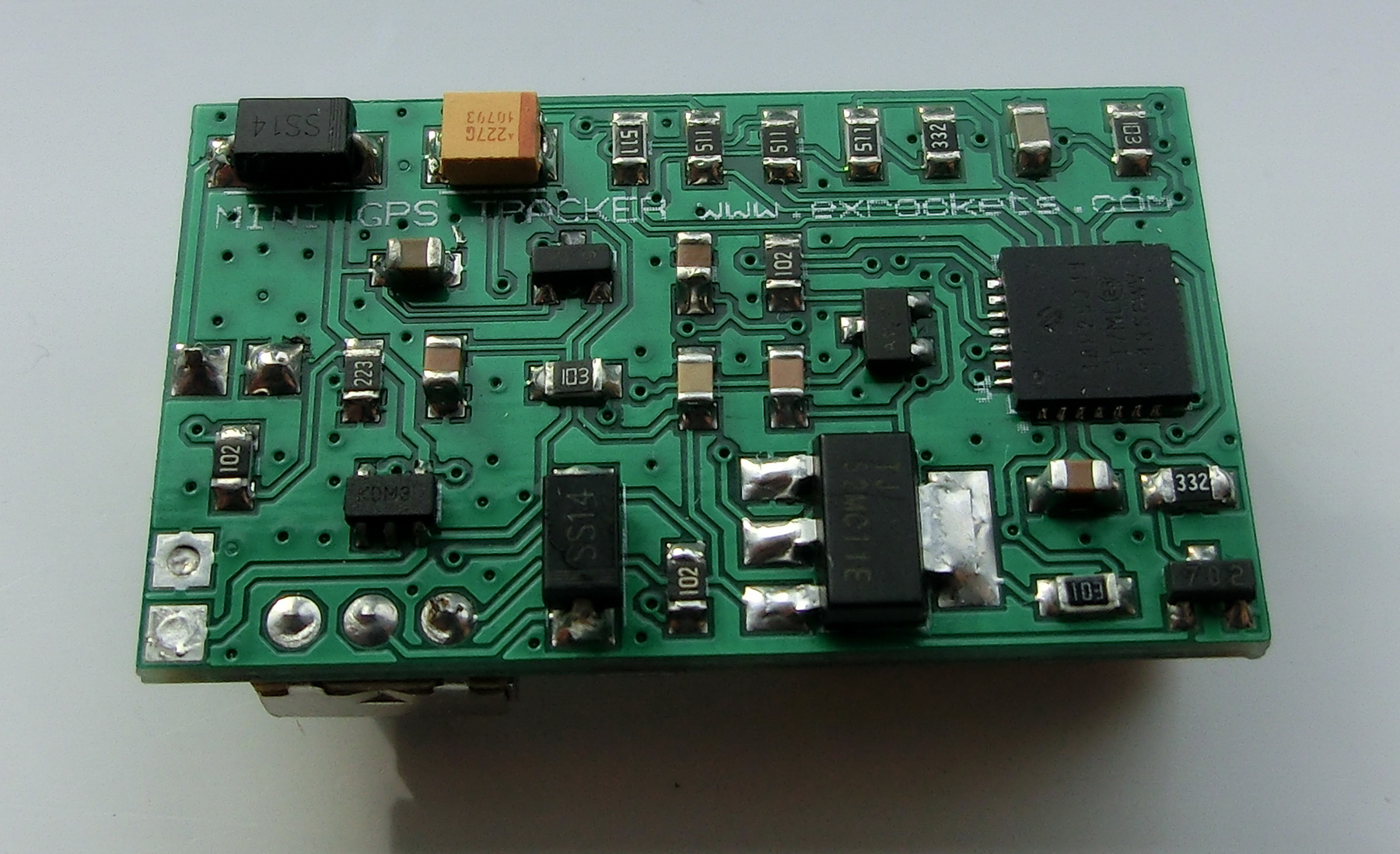
The design is based on my first GPS data logger – microSD card, GPS module, LDO power supply, LIPO charging circuit and PIC18F25J11 micro controller – all parts are easily obtainable from on-line sources like Ebay or Aliexpress. However some of the pins were changed, a LIPO charging circuit was added and the transistor switch for the SD card was put back in the design.
Using the GPS data logger is also quite simple:
– Connect to at least 3.5v power supply, the maximum is 21 volts.
– Place the SD card with SETTINGS.TXT file on it in the socket
– Switch the GPS logger on
– Wait until the SD card is initialized and all data files are created – thus wait until the SD card LED stops blinking
– If the SD LED remains solid on, then there’s something wrong with settings file or the SD card – for the exact reason please check the LOG_x.TXT file on the card (the file structure is explained further down)
– Wait until the GPS LED start blinking, indicating that the GPS signal is found and correctly decoded
– Press and hold for 1 second the SMD button to start the GPS data logging
– The NMEA GPS data stream will be decoded and recorded in the corresponding text data files (the file structure is explained further down)
– Stop the GPS data logging press and hold the button again and wait until all files are closed, hence until the SD LED remains solid off
* To safely remove the SD card you need first to stop the data logging and make sure that the SD LED is off when you remove the card
** The power consumption is the sum of the SD card power consumption, the GPS module and the data logger power consumption. If the sampling time is 10sec or less, then the data logger, the GPS module and the SD card power supply will be always on. The SD cards can draw between 2mA and 200mA depending on the manufacturer and the model. The data logger’s own consumption is 8mA and the GPS uses about 30mA when fully powered. If the sampling time is more than 10sec, then depending on the sampling rate, different power schemes will be used and some parts will be switched off to conserve energy between each data point record.
FILE SYSTEM:
SETTINGS
Write the sampling time in the first line. The sampling time is expressed in seconds. The minimum sampling time is 2s and the maximum is 99999999s. Make sure that there is a semicolon after the sampling time. After the sampling time, write the number of points to be taken. 0 means no point limit. The minimum point number is 1 and the maximum is 99999999. Make sure that there is a semicolon at the end.
SETTINGS.TXT – this file contains the sampling rate and the number of data points to be recorded. This file has to be present on the SD card for the proper function of the GPS Logger
LOG FILES
In total 7 files are created for each new GPS data logging. The name of each file indicates what information it will contain and “x” for the serial number of the record (not an absolute serial number but relative to the current number of files on the card)
LOG_x.TXT – contains the data logger system and status information
GGA_x.TXT – contains the $GPGGA message (Fix information)
GSA_x.TXT – contains the $GPGSA message (Overall Satellite data)
GSV_x.TXT – contains the $GPGSV message (Detailed Satellite data)
RMC_x.TXT –contains the $GPRMC message (Recommended minimum data for GPS)
VTG_x.TXT – contains the $GPVTG message (Vector track an Speed over the Ground)
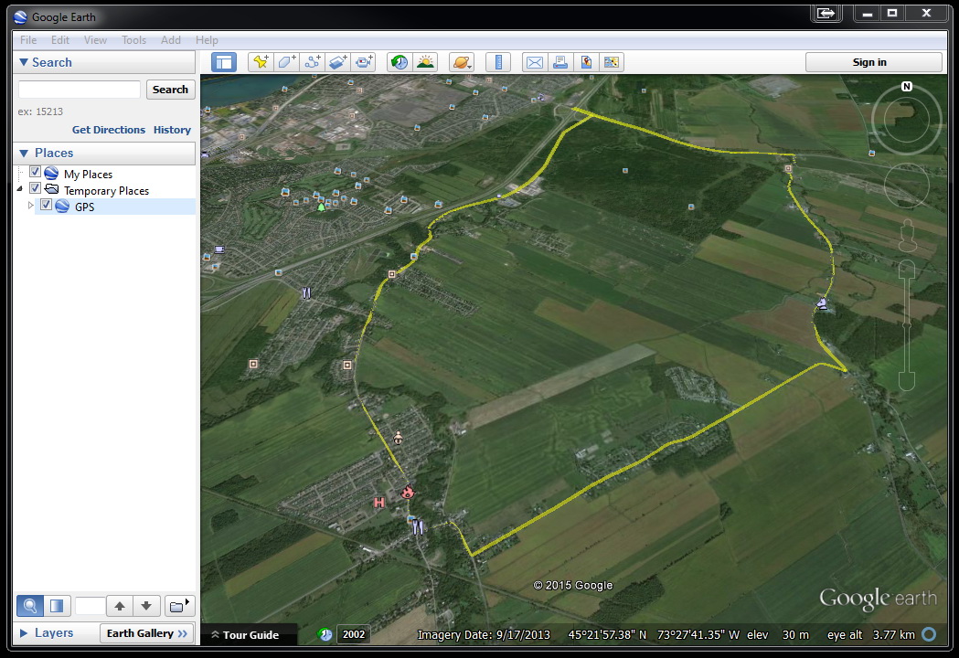
GPS_x.KML – this file has all data points converted from DDDMM.MMM to DDD.DDDDDDDD and it is in the format used by Google Earth and Google Maps to display a path in 3D over the ground. To use this file, simply load it in Google Earth.
The PCB manufacturing files and the MCU firmware can be downloaded from here:
GPS_DATA_LOGGER – CADCAM.ZIP
GPS_DATA_LOGGER – FIRMWARE.ZIP
Hi,
Do you have a BOM list for board with sd card and Charger?
Is the BTN a normally closed switch?
Regards
Peter
Hi Peter,
I posted a BOM for this project and updated the schematic to correctly represent a normally open button – thank you for noticing it.
With Best Wishes.
Hi Pinko,
Have got some PCB’s made.
Do you have a Part Placement plan.
I cannot guess the components from the image.
Regards
Pete
Hi Pete,
I uploaded an assembly file at the bottom of the page.
Regards
Hi Pinko,
Thanks for the info Page 4 has the info.
Also found these…..
https://www.aliexpress.com/af/openlog.html?SearchText=openlog&d=y&initiative_id=SB_20190216002353&origin=n&catId=0&isViewCP=y&jump=afs
See also Sparkfun Openlog for info
Regards
Pete