Large area Platinum electrodes or catalysts are often needed if you are interested in chemistry and science. Unfortunately large area Platinum mesh or foil are extremely expensive for the corresponding weight, the same is valid as well for Pt coated materials, not to mention their higher wear and the fact that they simply don’t work in some cases – for example anodes made from Platinum coated Titanium substrate are very popular but the actual Platinum that you purchase with it is very little and electro-coated Platinum wears much faster than rolled (forged) Platinum with highly compressed crystal surface structure.
So for a while I’ve been researching a technology and methods to make high quality Platinum anodes for chemistry (and other purposes). I was able to find very little practical information in the books and on the net. Thus I had to find for myself through trial and errors a lot of the little tricks that I’ll be sharing further down.
If you think this is something you would like to try, be advised that before you make your first platinum foil and anodes, you will need some equipment that you cannot buy but you have to build for yourself, or a friend who can do it for you on lathe and milling machine.
Further you will need a small Oxy-MAPP/Acetylene torch, please note that large torch is not going to work, a spot welder – something that you can build yourself as well or use a commercial one and of course some Platinum to work with. Add to that a lot of patience until you become comfortable with the process.
STOCK MATERIAL
PURE PLATINUM BAR
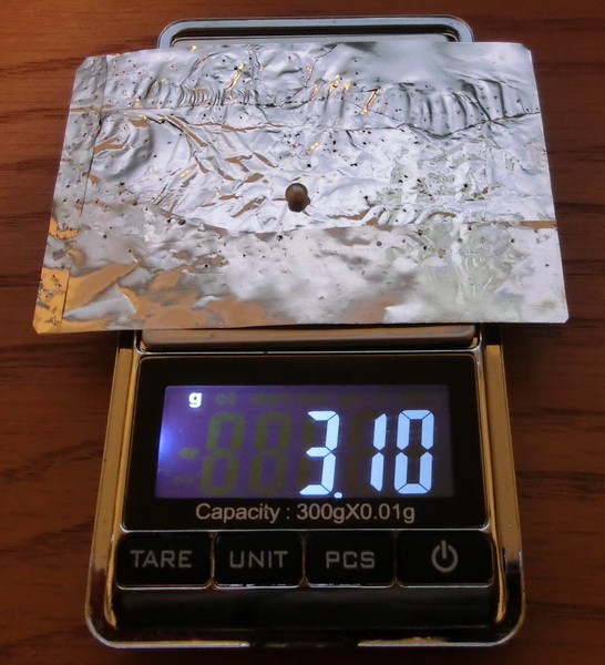
To make Platinum foil you will need … well Platinum. The best material is to buy a pure 99.9% Platinum bar from somewhere (I purchased mine from E-bay, APMEX). You probably won’t need more than 3gr Pt but it depends what you plan to do with the foil. I found out that one 5gr bar come cheaper than buying 3 x 1gr bars – so I took one 5gr bar.
SCRAP JEWELRY
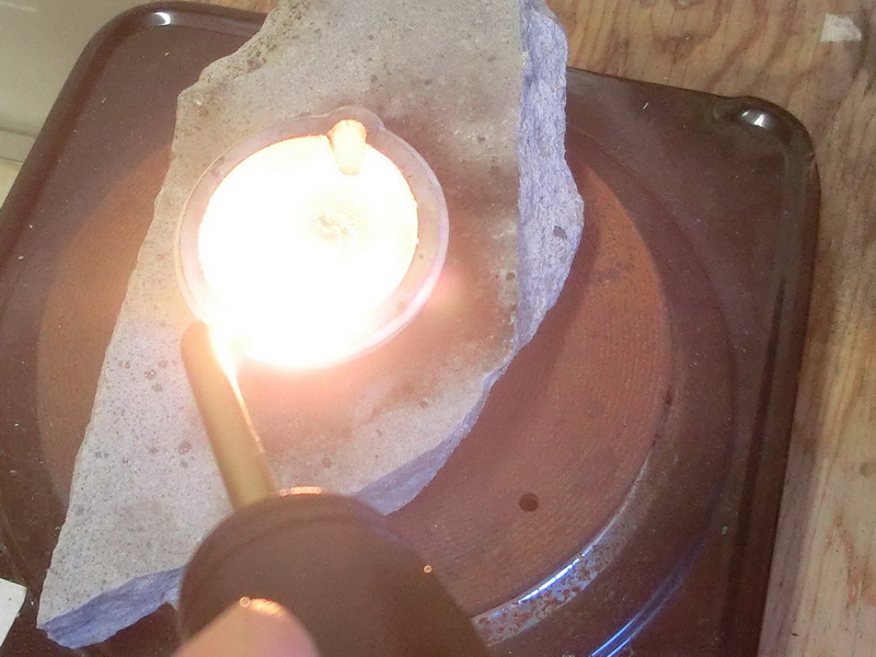
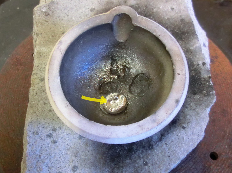
Another source of Platinum could be scrap metal from a jewelry shop – the picture below is me re-melting scrap Pt. However this is rarely pure Platinum and you have to make good calculations on how much pure platinum you are actually buying, it might come cheaper to simply purchase a pure Platinum bar on-line or elsewhere. Be advised that during the melting all non-noble metals will be oxidized and burnt away – so don’t be surprised if after melting the material you have less than the starting weight. Sometimes in the jewelry Platinum there is Iridium present to alloy it, which is not advisable (see next paragraph).
THERMOCOUPLES AND RELAYS
The last common source of platinum that I have used is thermocouples and relays. These sometimes can be found on the “black” market where defective thermocouples and relays are sold. Thermocouples contain Pt-Pd and relays Pt-Ir alloys. You should be well aware what you are buying and how much noble metal you are getting. Sometimes in the high-temperature thermocouples Palladium is replaced with alloys from non-noble metals. Although the Iridium and Palladium can be used alloyed together with Platinum in 99% of the semi-amateur cases where Platinum foil or anodes are required, the Pt-Ir-Pd alloy is hard, more brittle and difficult to mill.
MELTING
Platinum has high melting point (1765*C) and simple propane or propane-oxy torch will not be sufficient. You need an oxy-MAPP or oxy-acetylene or other high temperature torch. Further you can’t simply the big torch from the workshop, you need something smaller because you will blow away the Pt pieces and bits. In my case I am using a brazing oxy torch as the one on the picture bellow.
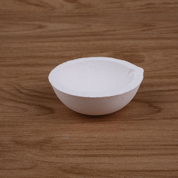
Further you will need a crucible to melt the Platinum into. The cheapest option is a small quartz crucible. Those can be purchased on Internet extremely cheap. Although the quartz has lower melting point than platinum, it has very low thermal conductivity and only a thin layer under the platinum gets molten.
Whatever gas you are using Platinum should not be melted in carbon rich media and you should always use an oxygen rich flame. So if you are thinking about induction heating, then you will need a graphite crucible but this is no-go as I mentioned. The reason is because the carbon enters in the molten Platinum and resulted alloy is very brittle.
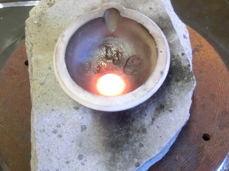
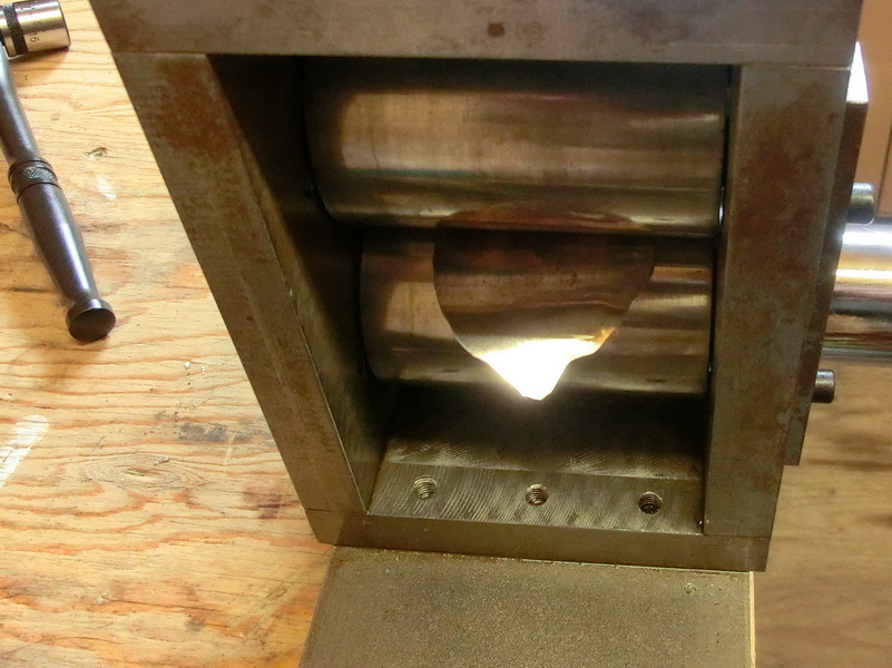
When the Pt starts melting, the surface tension will form a drop. The drop will become bright white and you will think it fully molten – it is not. If you stop here, the resulting bit of Platinum is very brittle and will crack and shear very easy, you can’t mill that material. My explanation (I am not a scientist and can’t claim this to be true) is that at this point part of the crystal lattice is molten, but there still individual crystals in it. So you have to continue heating the drop of Pt until is fully melted. But how you can know when to stop – you will notice that the more you heat it the brighter it becomes. At some point you will see a very noticeable decrease in the brightness of the drop, at this point it will also lose the spherical and take a more flat shape – now you can stop heating it. For this reason it is a good idea to direct the torch sideways so that the drop of platinum starts spinning in the quartz bead –if there are remaining oxides as impurities you can see the accumulating at the top of the drop as separate raised dome.
Now we leave the platinum bit to cool down really well. During the melting process as I mentioned earlier, the Pt will form a bed of molten quartz in the crucible. That molten quartz acts as flux and reacts with the oxides of the non-noble metals (if there were such) in the platinum, thus refining the Pt. Speaking of non-noble metals, by using oxygen rich flame and heating the Pt to well above its melting point we also allow most of the oxides to boil away as they have relatively low boiling point.
Back to our bit of Platinum – once it cools down it will separate by itself from the molten quartz bed leaving it intact. If we try to separate it earlier, it will break the quartz layer under it – this will add to the faster wear of the quartz crucible. But this is not really a problem, considering the very low cost of these crucibles.
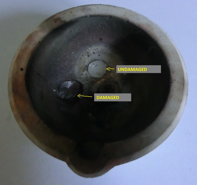
After the Pt bit is separated we do an inspection of the bottom. I noticed that if there is a hollow point in the bottom, which usually means that not all alloying elements burned always and/or that the heating wasn’t enough to completely melt the Pt which makes it extremely brittle (mentioned earlier). Thus we have to melt it one more time.
THE ROLLING MILL
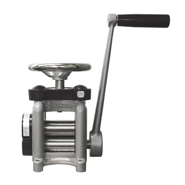
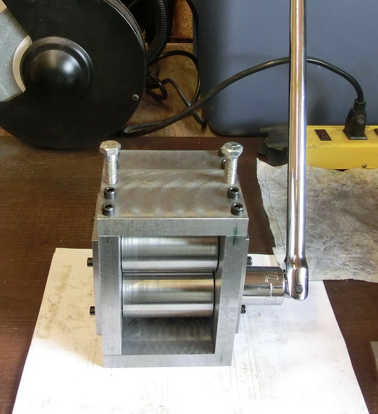
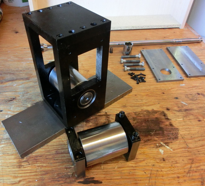
So we have refined our Platinum and it is time to start making the foil. For this purpose we will need a rolling mill like the one on the picture left. However these are expensive tools and having an access to a workshop I decided to make my own rolling mill as the one on the right.
If you decide to make your own rolling mill here are some remarks from my experience working with it.
As I said the idea for the rolling mills was taken from a picture on the Internet and the design was simplified. The best is if the both rolls are synchronized with a gearbox and the distance is being regulated in such a way that the pressure on both side bearings is equal – however this greatly complicates the design.
If the both rolls are moving synchronously they tend to “grab” the material much easier. If there is no gear transmission and the torque is applied to only one of the rolls then by increasing the diameter of the rolls we can overcome the problem with them not grabbing the material.
To make the spacing between the rolls equal I use two sets of cheap feeler gauges purchased from E-bay. Then I tighten the bolts by hand until the upper roll touches the gauges and then I further tighten it by hand – thus ensuring minimal difference between the left and right side.
Rolling Mill 1
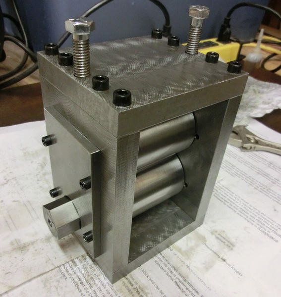
In this mill design the upper bearings are sliding in a stadium slot. Initially the pressure was applied directly on the outer shell but this led (not unexpected though) to bearing breakage. To avoid this problem I cut a slot as indicated in the picture and made a steel foot to distribute the force.
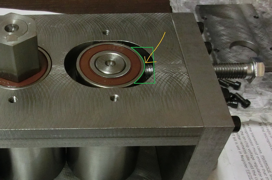
That worked but it seemed that one 3/8-16 Grade3 bolt on each side is not sufficient and when I was tightening the bolts to overcome the bearing play and tighten the elastic deformations (when the foil becomes thinner the elastic deformations in the entire construction become important) their thread got slowly damaged. Grade5 bolts started slowly damaging the thread in the plates, however not significantly. The problem now was that the bearing in the stadium slot did not have equal distribution of the load and eventually cracked where it was free without external support.
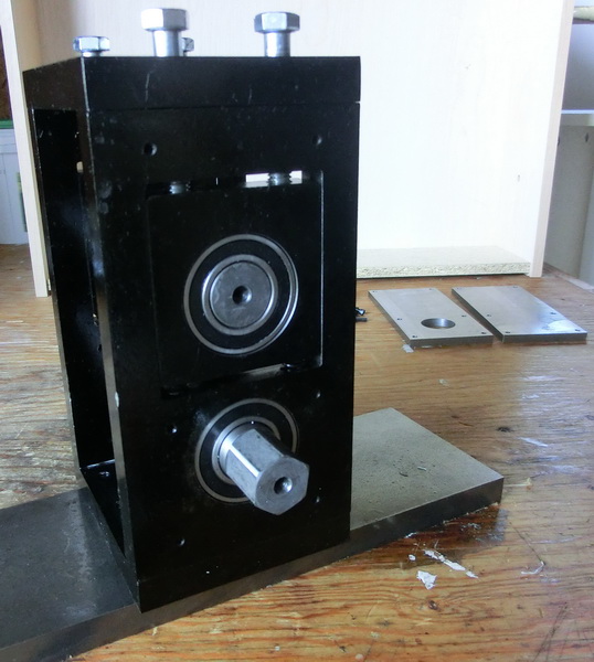
The bearings were relatively small and the end of the rolls did not have enough material to machine a hexagon, so I had to make a hexagon sleeve and a key way to transmit the torque from the wrench – but I forgot to leave space for disassembly of the sleeve.
Another issue was that the upper roll tends to tilt sideways or jump and bump if no material is pressing it up or because of the tension when the material is leaving the rolls.
The last issue was the material for the rolls. I used mild steel for the plates and the rolls and no heat treatment for the rolls. The hardness of the rolls wasn’t enough and the surface got marked from the platinum (which was unexpected). Eventually after quite a few of test rolling the surface of the rolls got relatively flat and self-forged with no or barely visible damage from the platinum.
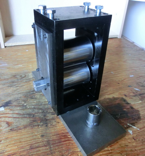
Rolling Mill 2
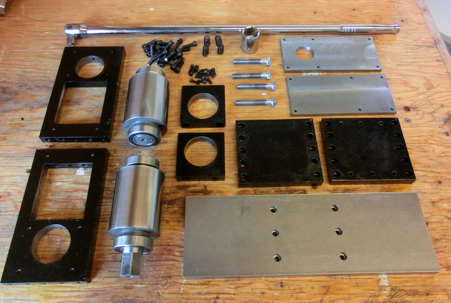
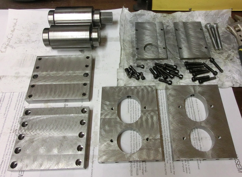
I used 4″x0.625″ cold rolled mild steel for the plates of the new mill. The rolls I made from 1045 steel and hardened them – I used what I had at hand, but if you have higher carbon content steel, it would be better.
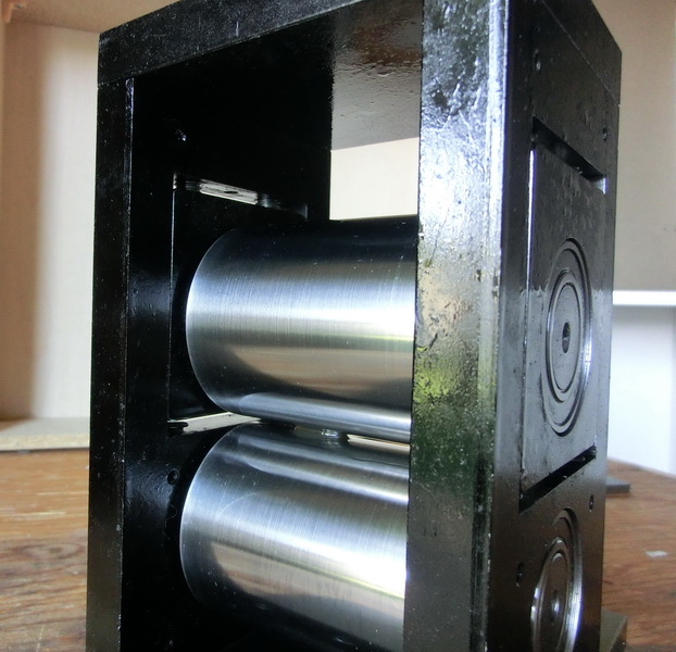
The first change was to put the upper bearings in a bearing box that will slide inside a slot on the plate. So the outer shell of the bearing is protected and can take a lot of pressure. To distribute the load and the tension I used two 3/8-16 bolts. For each bolt I made a small flat end step in the case to hold the bolts and the bearing case fixed. I placed a spring (found it in Home depot – 1 long spring was cut in 4 pieces) at the bottom of the bearing case to push and hold the roll upwards and to avoid bumping when the material leaves the rolls.
I also used larger size bearings 47x25x12 which made it possible to simply mill a hexagon at the end of the lower roll instead of using a sleeve.
I tested the new design by tightening the pressure bolts as much as I could and turning the rolls. They did not break nor got the threads damaged but the bearings inside got damaged from the excessive force. So I guess flat roller bearings would be better but they are so much more expensive that it is not worth it and I will need to adjust the thickness of the side plates to accumulate the extra width. But again, I don’t need that extra force unless I am planning on rolling some tough materials, but then I will need harder surface on the rolls.
Just as a note if you decide to endeavor making your own rolling mill, you don’t need more than 6-8 mm of distance play between the rolls and you should leave enough space on the lower side of the slots (those for the bearing casings) so that the springs have enough space to tighten when the roll is at its lowest point – otherwise it will be pushing on a completely closed i.e. solid spring.

ROLLING THE PLATINUM TO FOIL
Before you start making the foil you should not know that this is a slow process and requires some patience and perseverance thus don’t give up if you don’t get it right from the first or second or … try.
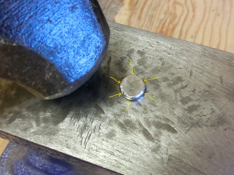
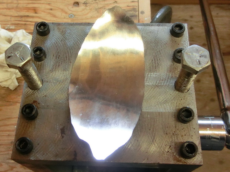
The first step is to hammer on an anvil or something suitable our bit of Platinum that we melted to a thick flat pancake. Don’t hurry and try to smash it with one hit – it’s not good to mill afterwards and you risk losing the Pt if the bit fly away, take your time. From time to time turn perpendicularly the Pt bit and lightly hammer the narrow side (indicated with arrows) until you get a coin-shaped form. This is necessary in order to reduce the shear at the edges later during the mill process. There is no need to flatten the piece too thin, just enough for the rolls to be able to catch it.
Once the Pt bit is flat enough we start rolling through the mill. Initially you will need to push the Pt bit with fingers (do that only in manual rolling mills for understandable reasons) so that the rolls can grab it. You have to this until the piece got thin enough so that the rolls can easily grab and hold it. This is the most tedious part.

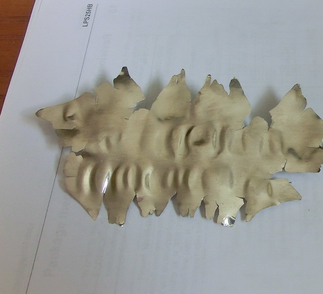
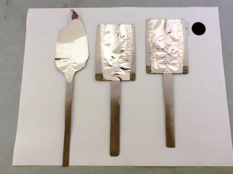
It is VERY IMPORTANT that you don’t change direction of the elongation and you do that ONLY ONE TIME! If you start changing the direction of elongation the foil will start shearing at the edges towards the center and you will get something like in my early attempts.
That means you don’t turn the Pt piece left and right until you have as length the width that you desire. So if you plan to make a 30mm wide foil, you mill in one direction until you have 35-40 mm length and then you turn 1 time 90 degrees and you continue with your former length now as a width.
From this point on it is important that you don’t lower the thickness more than 5% at the time and you pass the sheet 3-4 times between the rolls before you change the thickness again. When you tighten the rolls you should pay attention that you turn them equally.
If the sheet starts showing shears on the outside don’t get worried, the outer edge has to be trimmed anyway and this is normal as long as you don’t get something like the picture before the last ones.
When the sheet starts thinning and especially when the foil is thin I start putting oil (automobile oil), a lot of oil, over the foil between the passes. This helps to keep the pressure over the foil equal and prevents the foil from slipping between the rolls – I know it doesn’t make sense, but that’s what I observed.
Once the foil is still thick when it becomes longer more than 4 times the width I will cut it in two and continue from there. Trying to make long foil (more than 5 times the width) didn’t work for me, it starts warping and tearing in the middle.
During the entire process the platinum gets self-hardened and needs tempering every time you tighten the bolts. In some books it is written that pure Platinum does not self-harden but in my experience 99.95% pure platinum bar did. In fact the hardened Pt sheet became and behaved like spring steel.
Tempering is done with a propane torch, it is cheap and easy to use and the temperature of the flame is not high enough to melt the platinum. You simply heat the platinum sheet/foil until it is bright red and leave it to cool down.
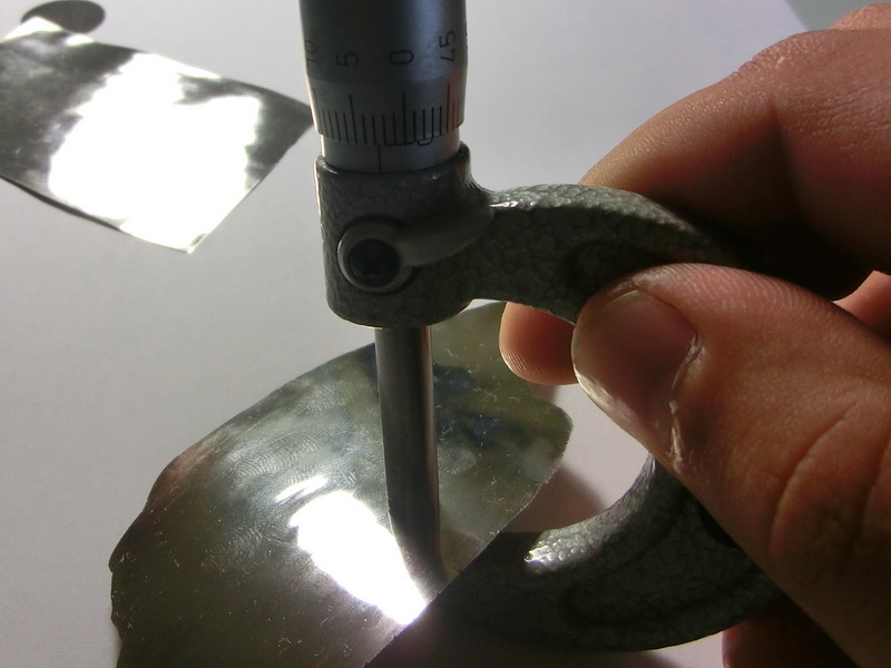
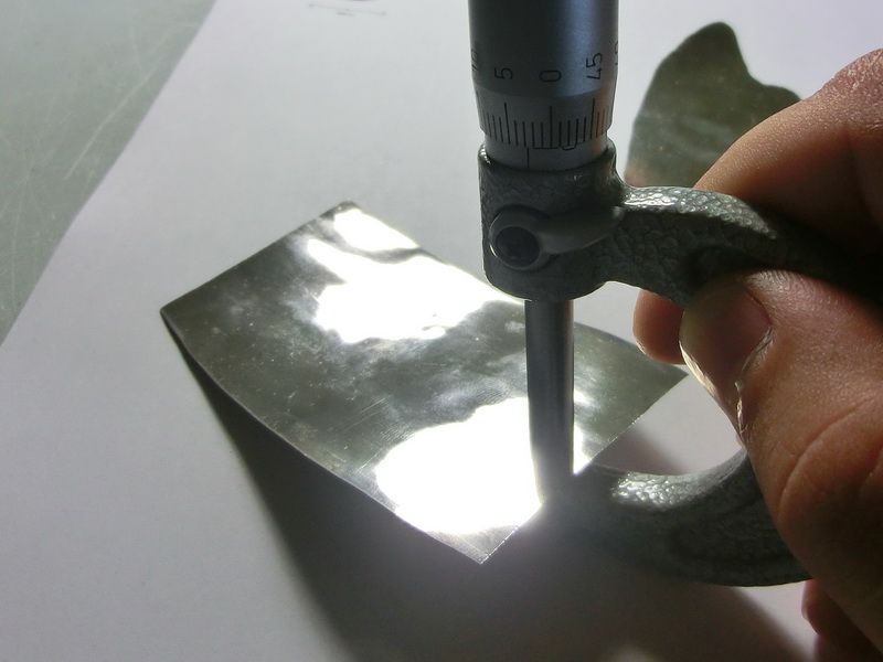
Once you have reached the desired thickness you can trim the foil to a rectangular shape and melt the cutouts to make another foil sheets and so on until you have very small amount of Pt left, which is difficult to make in to a rectangular shape.
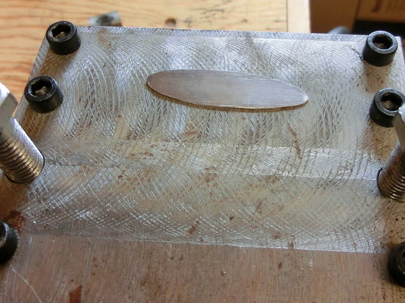
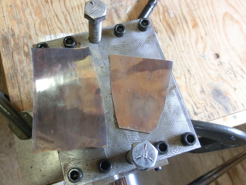
The foil sheets on the book page that you see next are made from 5gr Platinum and 0.5gr was left which was rolled only in one direction to make a Platinum strip shown used in the picture after that.
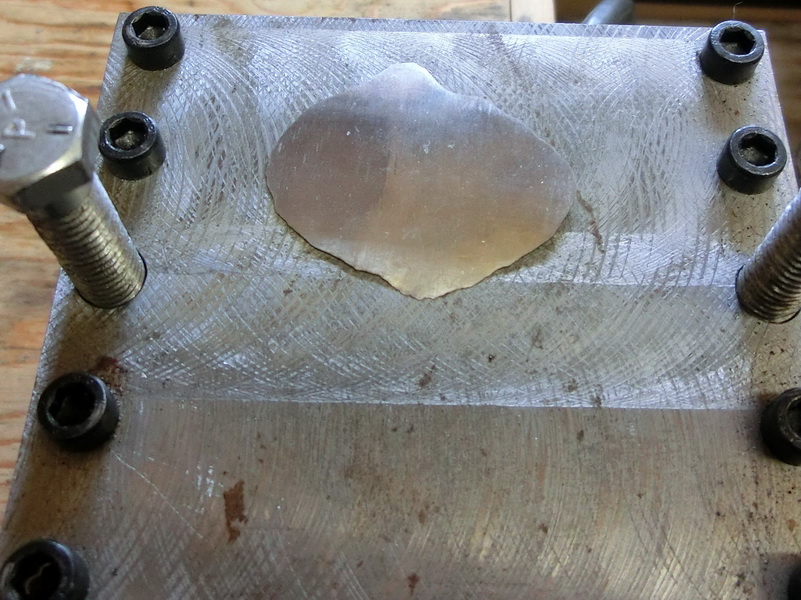
On another instance when I was making Platinum foil, there was no need to trim the foil to a rectangular shape and I simply left it in the original form.
MAKING PLATINUM ANODES FROM THE FOIL
To make usable anodes the making the foil was the first step from the process. Now we have to make the actual anode unless you are planning to use the foil itself as catalyst. So it would be very useful if we can weld the platinum.
Graphite welding Platinum to Platinum
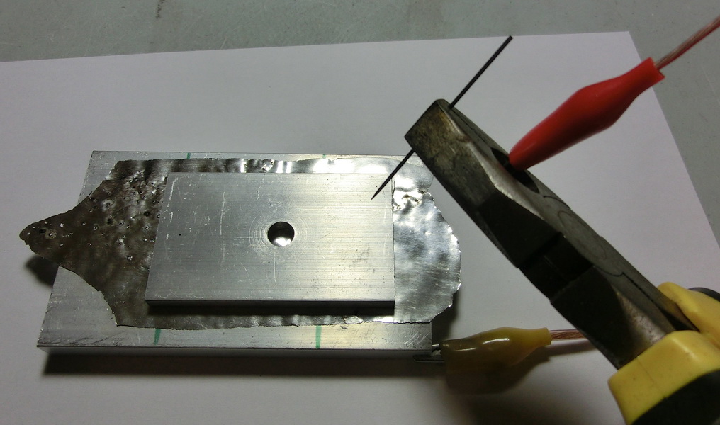
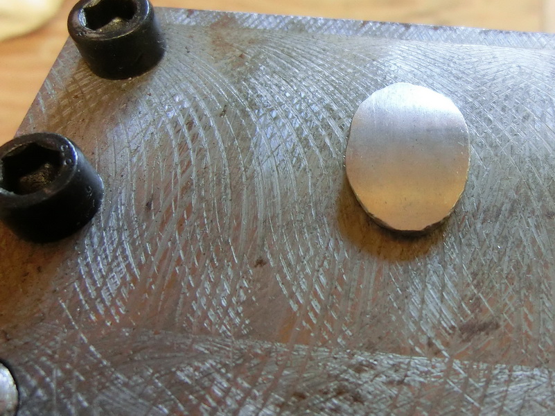
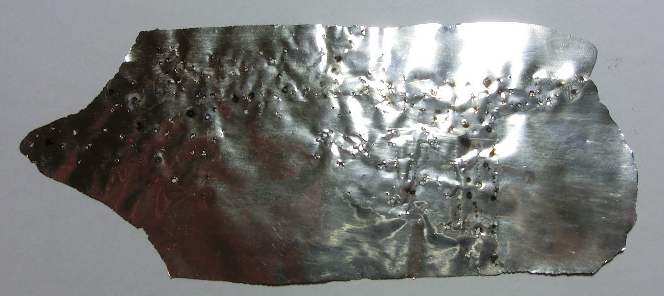
Welding Platinum to Platinum is not that difficult at home. All you need is a computer power supply which has high current output on the 5v bus and 0.9mm graphite fill for a pencil. You can use pliers to hold the graphite and connect the positive output to the pliers where the negative end is connected to an aluminum base over which the Platinum foil is pressed down. You use it by making a contact with the graphite over the foil – at the point of contact, the graphite starts burning and locally reaching high enough temperature to melt through the Pt foil. Thus if you melt through two or more sheets while they are being pressed down, you get a small hole with melted together edges which is enough to transfer sufficient current later for the chemical process.
This is very handy technique because you can assemble Pt electrodes from trimming cutouts or irregular shapes. They don’t look as nice as the other electrodes but are equally useful and the advantage is you can assemble any size you want.
Spot welding Platinum to Titanium
Making Platinum anodes for perchlorates has some specific touches. Usually the process requires passing high currents trough the electrode for good efficiency of the perchlorate cell. Another problem is that the working conditions in the perchlorate cell are very aggressive and only few materials can withstand it without corroding. So bringing the current to the Pt foil is not a trivial problem.
One way is making an entirely Platinum based anode – but it is not practical for several reasons – it is too expensive and Platinum has high electrical resistance which limits the effective current distribution and density close to the electrical contact points.
I have seen and done myself attempts for using a normal conductor to the platinum and insulating the contact point – but these types of anodes last only for short period before they fail and introduce significant contamination to the perchlorate cell.
Another type of Platinum anode I’ve seen is Pt wire connected to a normal wire inside borosilicate glass tubing whose end was melted and pressed down. The disadvantage is that you can use a thin wire only – in my tryouts thick Pt wire or foil have too much of expansion and crack the borosilicate glass. The thin Pt wire significantly limits the current that can pass and the effective working area is mostly around the connection point with the foil – basically you need multiple connection points for equal distribution of the high current through the thin foil.
Anodes made from Platinum coated Titanium substrate are very popular but the actual Platinum that you purchase with it is very little and electro-coated Platinum wears much faster than rolled (forged) Platinum with highly compressed surface structure.
As I said at the beginning in the amateur (and not only) practice often Platinum coated Titanium is used. One of the reasons is that Titanium surface passivizes when exposed to the aggressive conditions in the perchlorate cell and stop conducting current, thus there is no corrosion. This led me to the idea of WELDING PLATINUM FOIL TO TITANIUM CONDUCTOR where the titanium will serve as current conductor. Welding Titanium at home is not an obvious task, however I know that Titanium can easily be contact-welded.
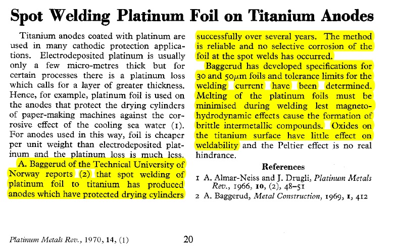
For that purpose I built from a scrap MOT my DIY SPOT WELDER and tried spot-welding Platinum over Titanium. After few attempts I got the settings right – high current but less inrush current, longer double pulses are required.
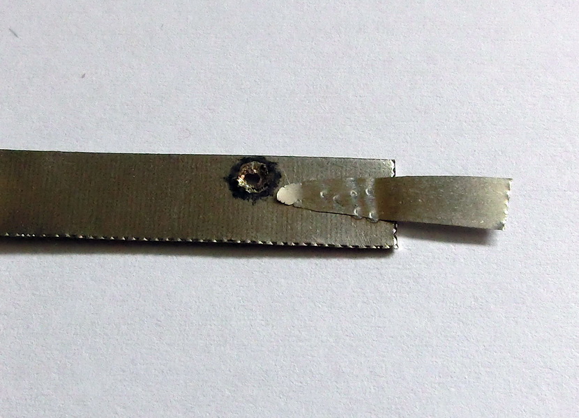
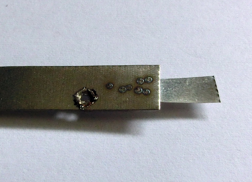
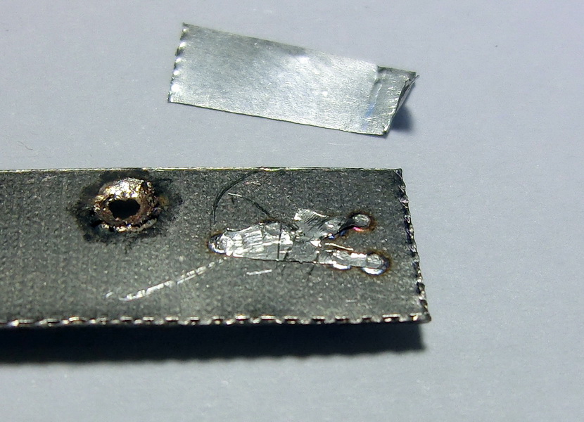
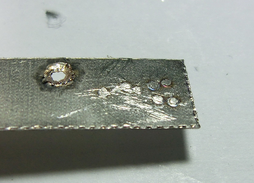
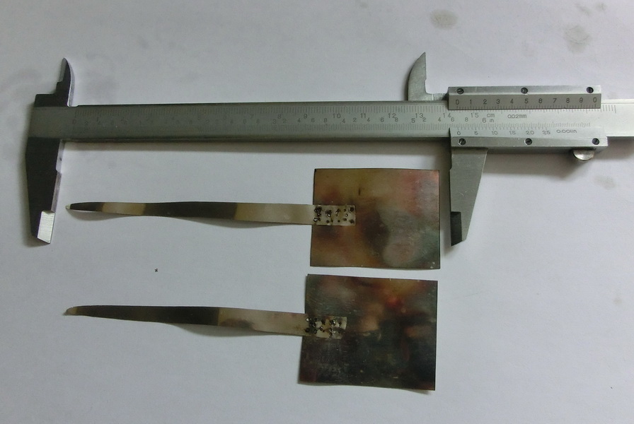
As you can see on the pictures above, at the spot of contact the molten Titanium and Platinum form an alloy which is mechanically sound and conducts electricity. So I built my first Titanium-Platinum anode for perchlorate cells.
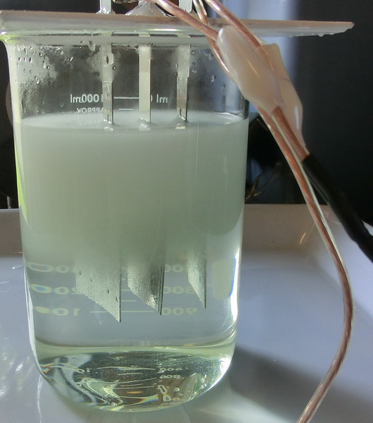
The thick titanium strip conducts high current to the Platinum foil and ensures equal current density throughout the Platinum foil via the multiple spot welds. On other hand the exposed Titanium and the outer side of the welds becomes quickly passivated thus ensuring no corrosion on the Ti strip or inside the Titanium-Platinum welds and all the Platinum is used for the process.
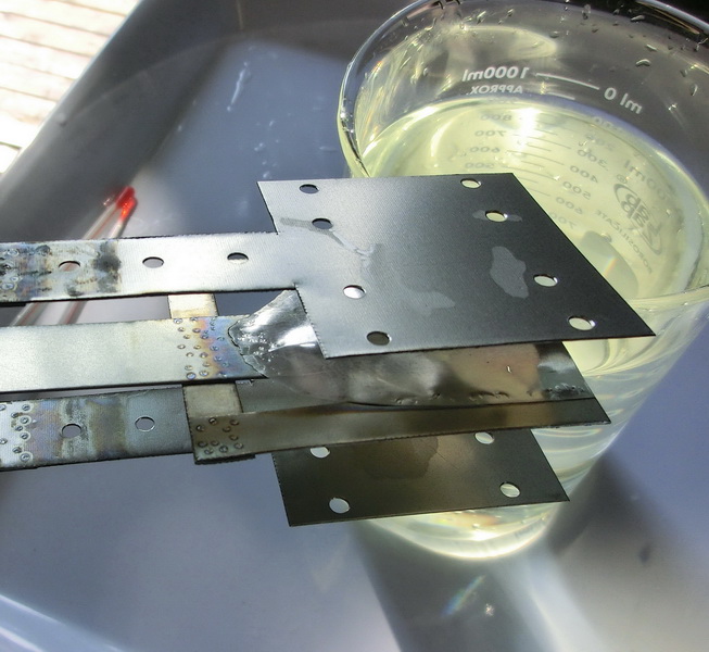
The so built electrode had been working for several months in a perchlorate cell with no signs of wear or any other problems. Thus the idea of spot-welding Platinum over Titanium proved to be sound and practical, allowing avoiding many problems in the home amateur science projects.
P.s. I really enjoyed and learned a lot while researching and working on this personal project. It was very satisfying to see the final result coming out so well and hope the information and ideas stated here will be helpful to other “home scientist”.
Fantastic work! I wonder if the platinum foil and the titanium could be attached by rolling them through the roller machine together. Certainly the surface of the titanium would need to be etched beforehand. Also, I know you’ve mentioned it in your chlorate cell page before, but it’s worth reiterating that only titanium of grade 1,2,3, or 4 is suitable for an anode.
Thank you for your support Lucas. Indeed Ti Grade5 has too much aluminum in it and should not be used.
I am afraid that the method that you propose has some disadvantages. Etching Titanium is not an easy task as far as I know. But the main problem in my view would be guaranteeing the low-resistance electrical contact between the Pt foil and the Ti frame.
If there is no real fusion between the metals, unlike the spot-welding where both are alloyed in the weld, eventually some oxygen will creep to the Ti surface and it will get oxidized which is going to act as an insulator and the electrode will fail.
What if you were to roll some electroplated Pt over Ti sheets to bond them together and smooth the surface. Perhaps get the best of both and possibly with a bit thinner total Pt coating.
In the past people used to heat and flux weld sheets of silver onto copper and then roll it into thin material for making plated silver ware. This was done before silver plating was practical and pure silver was too soft and expensive.
It is a good idea worth trying, the platinum coating will get smoother and denser. I am just thinking that the very different tensile strength and hardness of both materials will result in the Platinum “flowing” over the Ti instead of bonding to it. Thus instead of strengthening the cohesion between Ti and Pt it will weaken it but only test can say.
Thank you for your great job !
Impressive, really !
Can you tell what kind of glue/resin did you use for hold the electrodes in chlorate/perchlorate cell ?
I’ve test epoxy : not perfect, but hold some months
Acrylic resin bi-component : good resistance to ClO3 hold but not a long time mechanically.
Thank you if you can share your experience !
Hello,
the top plate, which is holding the three TI-Pl electrodes, is made from PVC. I used dissolved PVC to seal the through cutouts in the PVC plate and hot-glue on the top site for mechanical strength. From time to time I re-heat the hot-glue with a heat gun just to re-adhere it to the electrodes if needed.
Regards.
The linked patent shows how the platinum can be protected from contamination and damage by the rollers by covering with a layer of copper. Not sure why they wanted a stripped electrode unless the counter electrode had to be larger than the active platinum surface.
https://patents.google.com/patent/US5761799
Super impressive work and perseverance! You’ve given me hope that I can spot weld 0.1 mm thick Pt foil to grade 2 Ti – hopefully, without too many failed attempts. Thanks for sharing your facinating project and useful findings!
How thick can you laminate it? How thick is your platinum electrode?