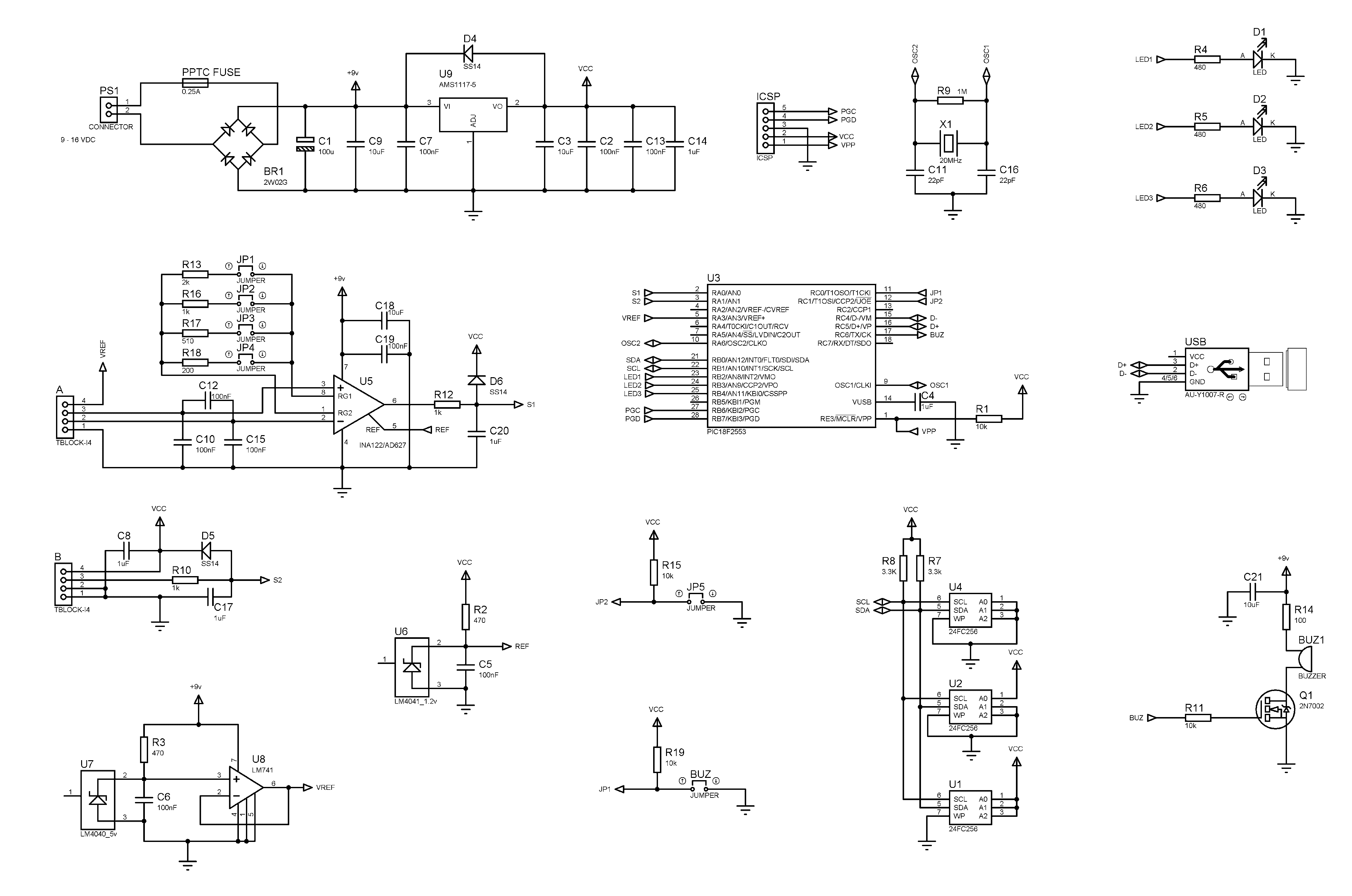
his DAQ schematic is a new improved version of my old ROCKET THRUST STAND SMALL DAQ SYSTEM. The small changes that I made are as follow:
- A small PPTC fuse was placed at the input to limit the current drawn from the battery in case of short circuit
- The 5v excitation voltage is buffered now through an OPAMP in order to supply higher current if needed
- The output of the instrumental amplifier was shifted to 1.2 volts for more accurate measurements and calibration
The rest of the DAQ system remains the same:
– This DAQ system can be powered from 8.5 volts to 12 volt DC or AC sources, where the polarity of the connectors is not important. If the supply voltage drops below 8.5v the system still will be working but the readings will no longer be correct
*Please note that some rechargeable “9 volt” batteries have actual nominal voltage of less than 8.5 volt
– The total consumption while recording the test is about 50 mA
– It can record up to 3 tests before you will need to erase the memory
– The total test time allowed per bank of memory is approximately 16 seconds
– Can work in autonomous mode where the data is stored in memory or in real-time mode by sending the data directly to the PC
– In stand-alone mode the time stamp is 0.002 seconds
– In real-time mode the time stamp is 0.01 seconds
– Circular buffer that keeps data for 1/4 second before the detected start
– Automatically detects the start
– Low-voltage detection
– There are two ports – PORT A and PORT B
– Port A is intended for load cells (this is normally where the thrust stand is connected)
– Port B can be used to connect another source to be digitized where the input voltage shouldn’t exceed 5 volts (although there is a clamping diode that should prevent damage to the system if this voltage is surpassed)
– JP1 (the one next to the USB port) will enable/disable the buzzer
– JP3 to JP6 will select the system gain – 100, 200, 500 and 1000 times. This is to say that the signal from the load cell will be amplified that many times
– The small button on the bottom side is intended to provide the possibility to format the device even when it is not connected to a computer. To prevent accidental erasure there is a procedure to follow before the memory can be erased
LOW-VOLTAGE DETECTION:
This reference diode is configured to work in the range from 8.5 to 12v with a standard load cell load of more than 300 Ohm. The LDO regulator works down to 6v while keeping 5 volt output. However if the power supply drops below 8.5v the output from the reference diode (under load) will be lower than 5 volts.
The system will compare the voltage output from the 5 volt reference diode and the LDO regulator. If there is a difference of more than 50 mV from both outputs the system will stop and give a continuous audio signal meaning that the battery output is less than 8.5 volts.
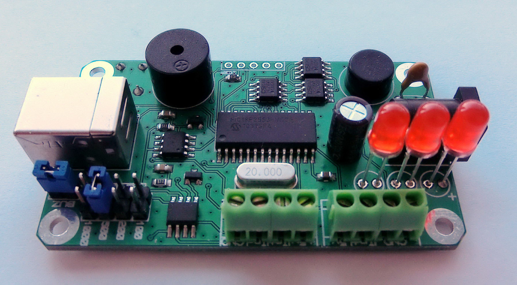
NEW PCB
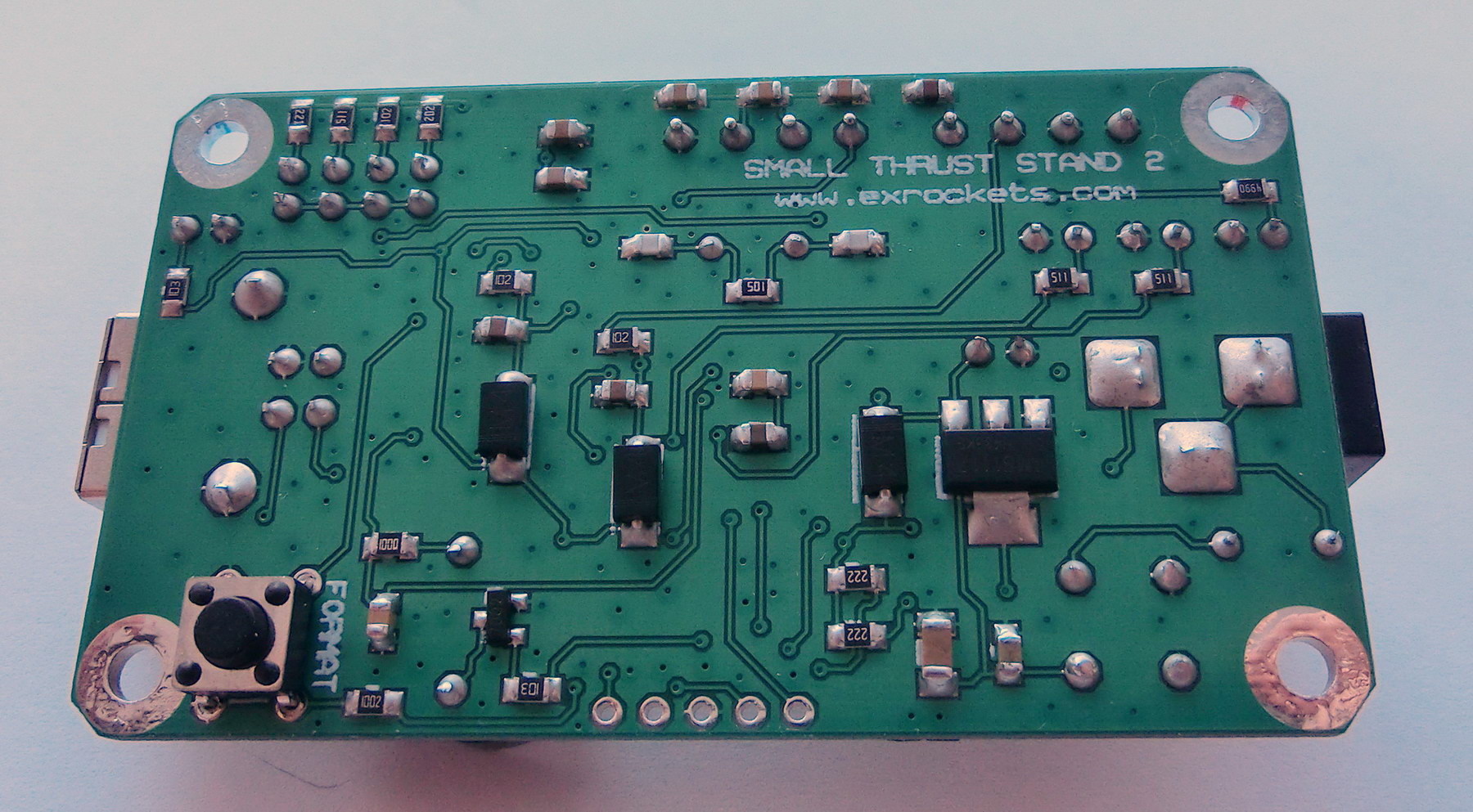
OLD PCB
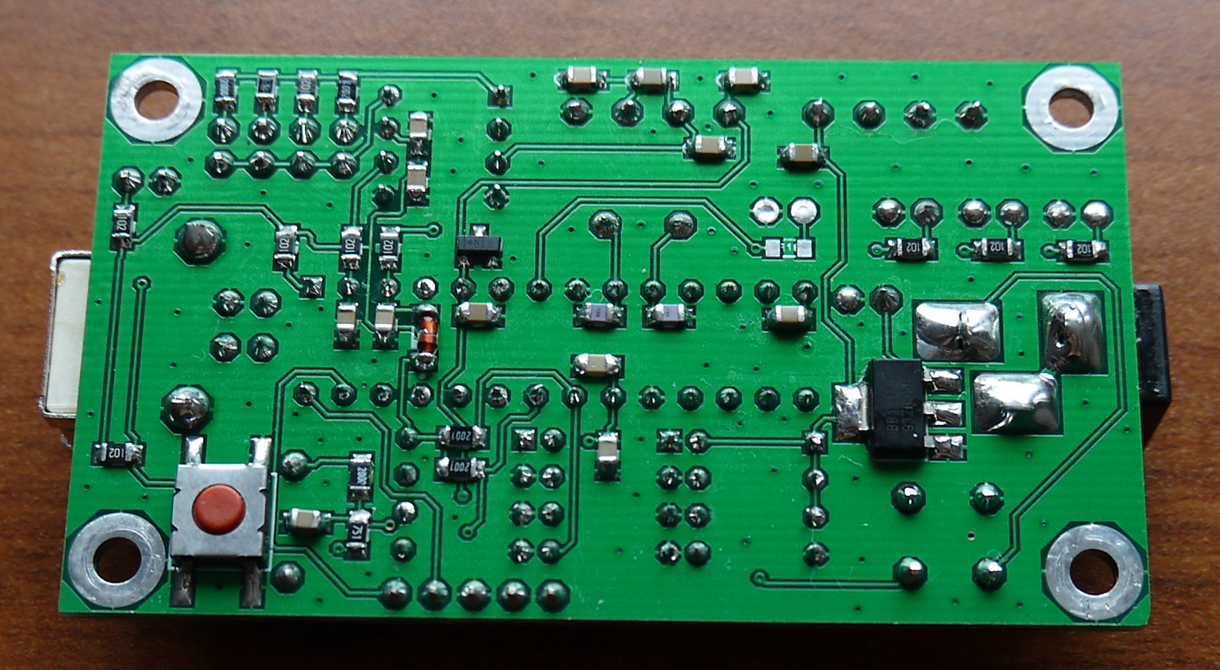
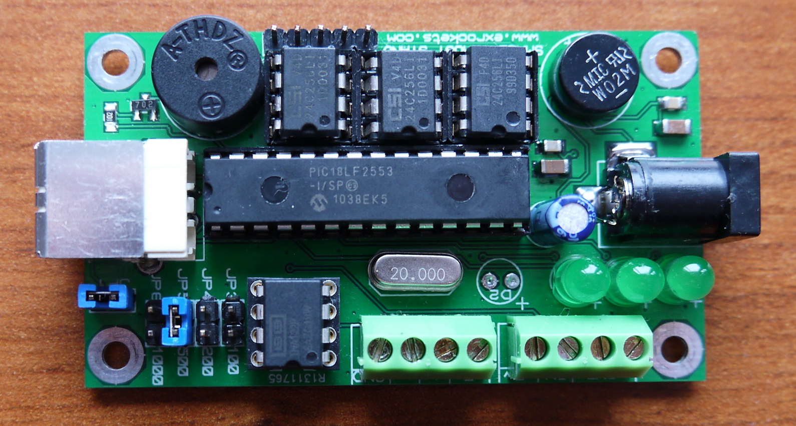
The PCB size and the main components remained at the same place, so the case from the old DAQ described here (ROCKET THRUST STAND SMALL DAQ SYSTEM) can be used with this DAQ as well.
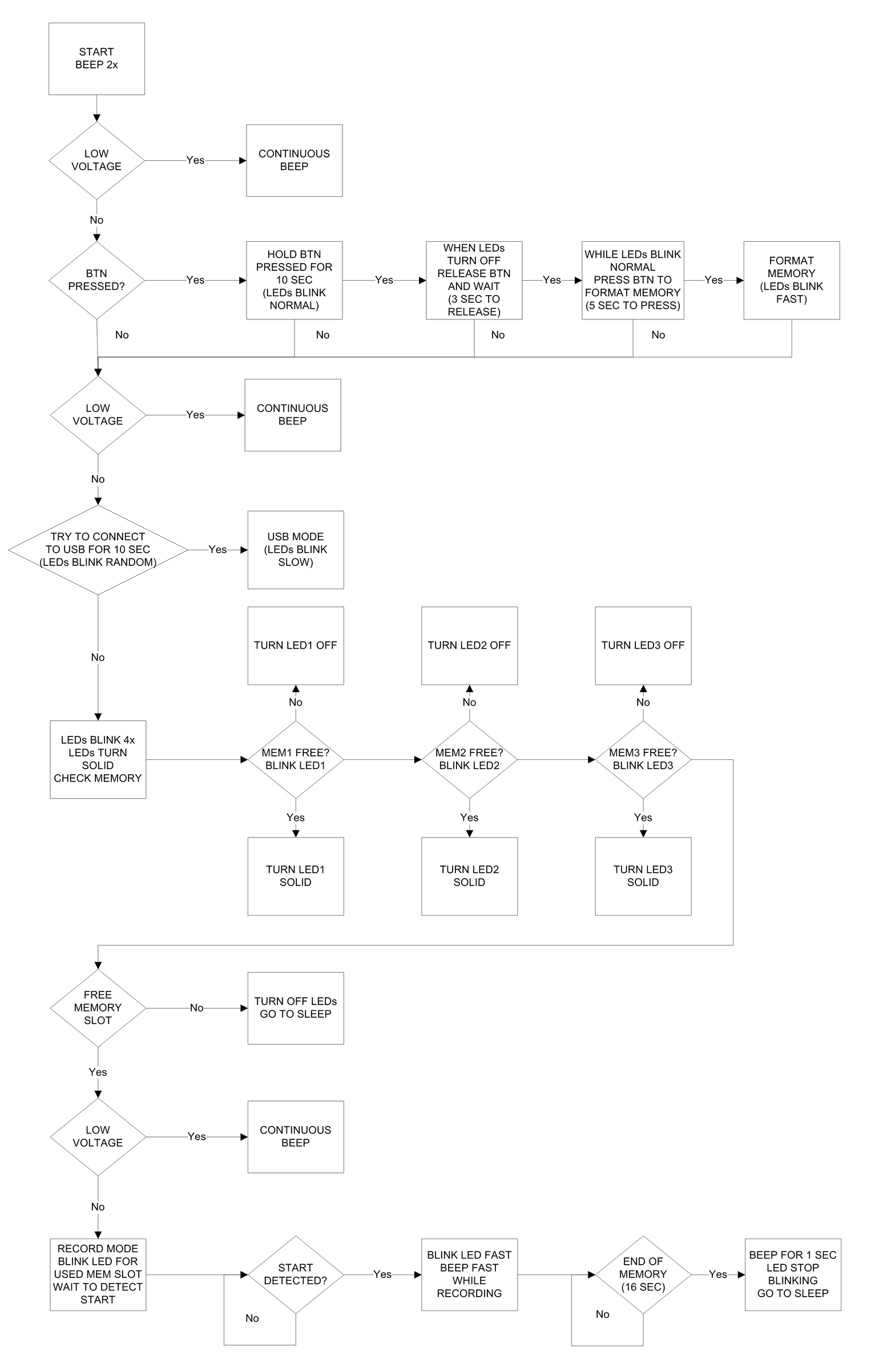
The firmware was modified to account for the changed ports to which the LEDs are connected, but the logical flowchart remains unchanged.
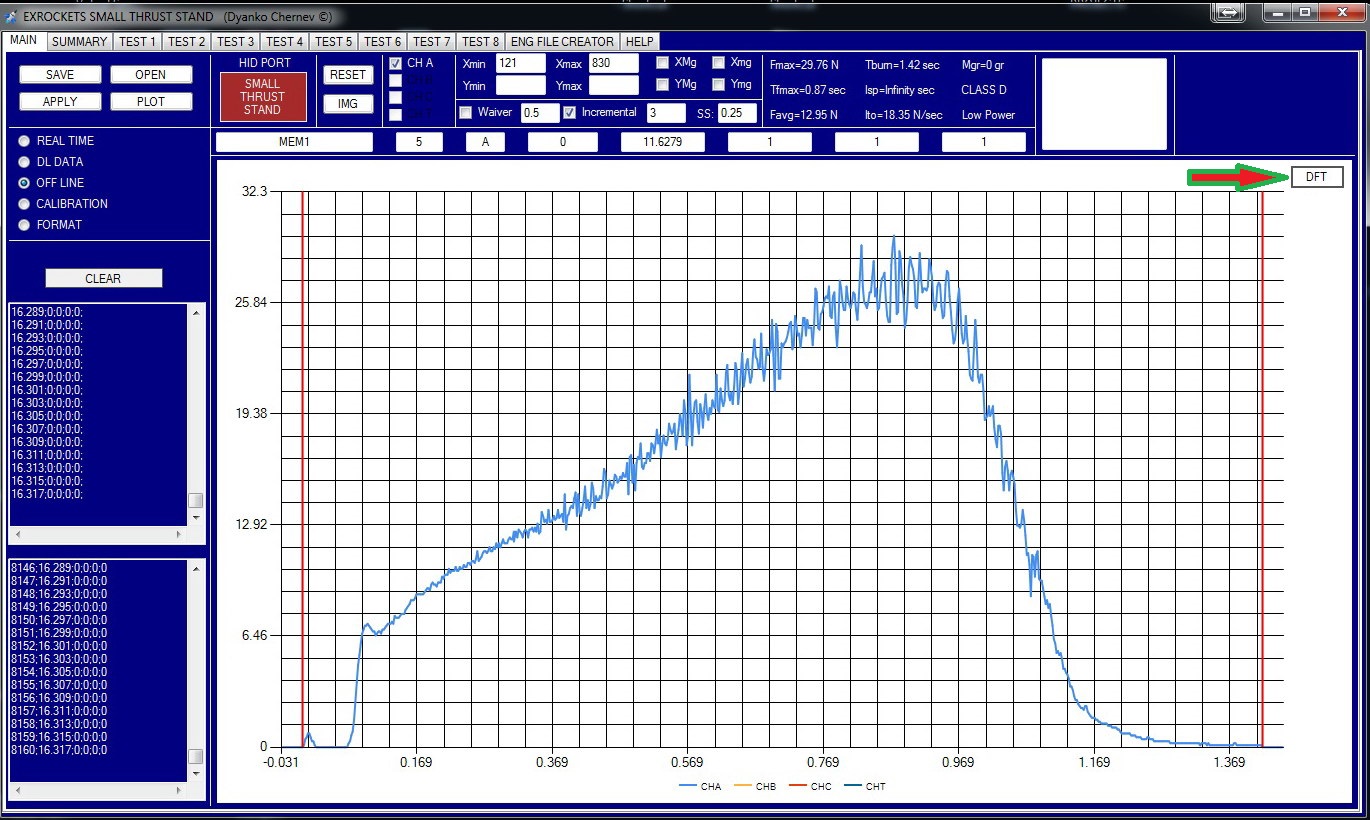
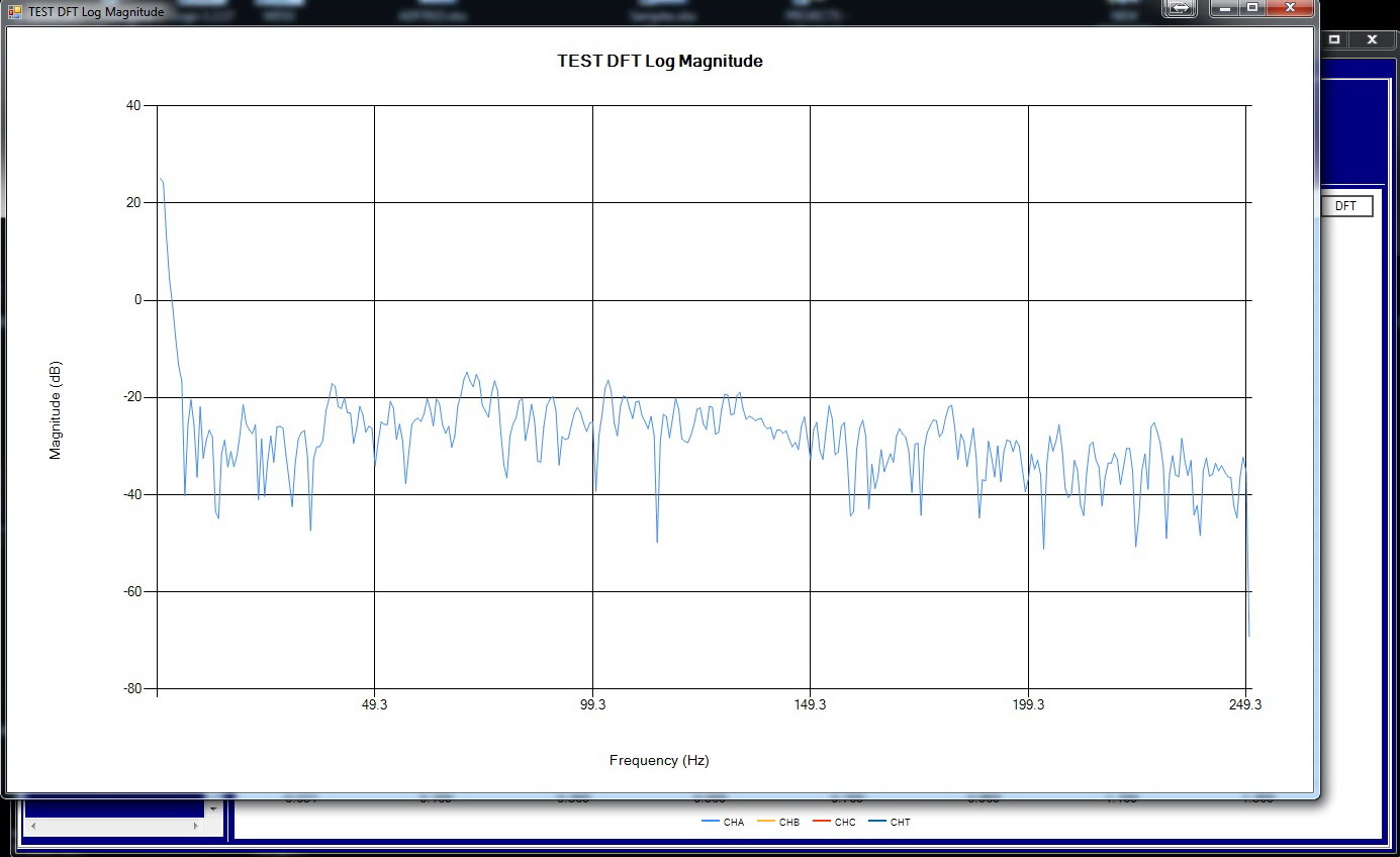
 I used the opportunity to fix some bugs in the software and also I made a nice addition to the functionality by adding a Furrier analysis for stand data. The DFT was done by implementing the DSPLib library.
You can see in the next two screenshots the frequency spectrum of a real motor test from RocKI.
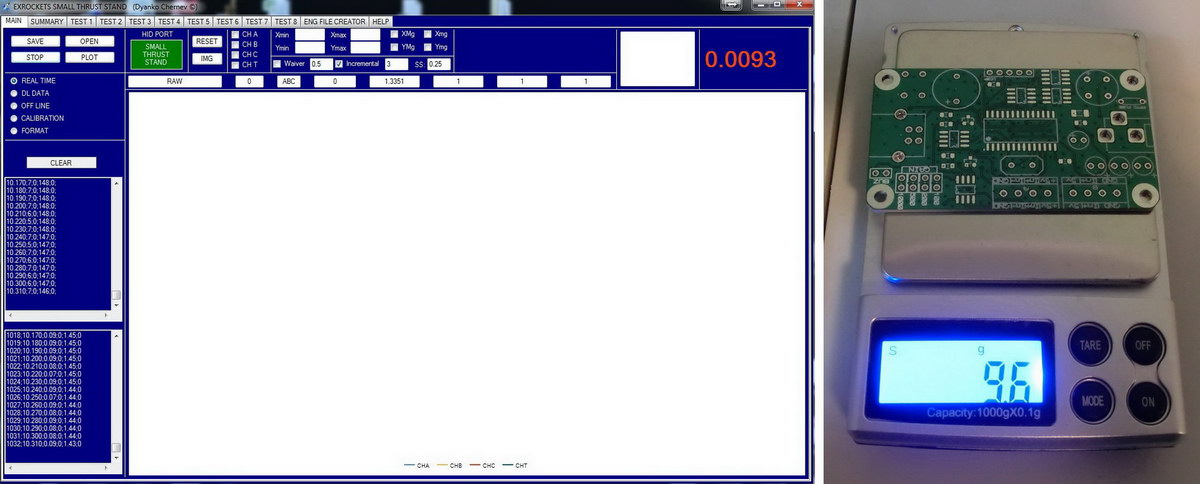
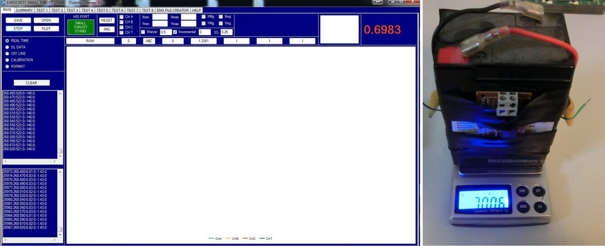
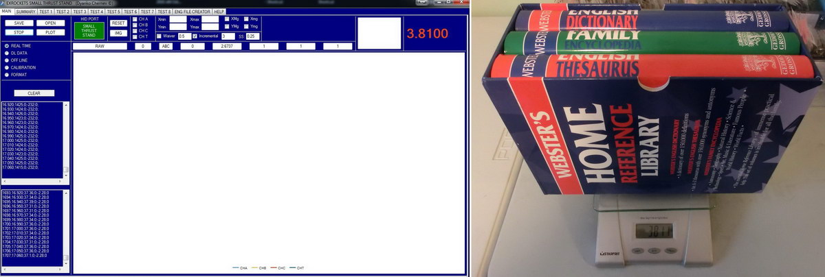
My initial intention was to use the thrust stand with calibration weights of at least 1 kg which allows you to use 1kg load cells. But I have been already asked several times if the thrust stand DAQ can be used for micro motors where thrust in the gram-range will be measured.
To do that you will have to use a load cell, rated less than 1 kg (for example 100gr, 200gr or 500gr load cells). However in this case you will need calibration weights of less than 1 kg. To implement this function I had to make a minor modification in the firmware as well as in the software application. Now you will have the option of choosing what is the measurement unit used for calibration i.e. kilograms or grams and the calibration weight range is either from 1gr to 255gr or 1kg to 255kg.

SMALL_THRUST_STAND_2_CADCAM_PCB_FILES
SMALL_THRUST_STAND_2_HID_FIRMWARE
SMALL_THRUST_STAND_2_APPLICATION_1.06
Leave a Reply