I finished this laser wall trigger for my HIGH RESOLUTION AND ACCURACY CHRONOGRAPH. The purpose of this device is to generate the trigger start and stop impulses for my chronograph as soon as an object disrupts any of the laser beams.
So if I have two laser walls (with one or more laser beams on each of the walls) and they are placed at a given distance from each other, as soon as an object crosses the first laser beams a start impulse will be generated and the chronograph will start counting. Then as soon as the object crosses the second laser beams a new impulse will be generated and the chronograph will stop counting.
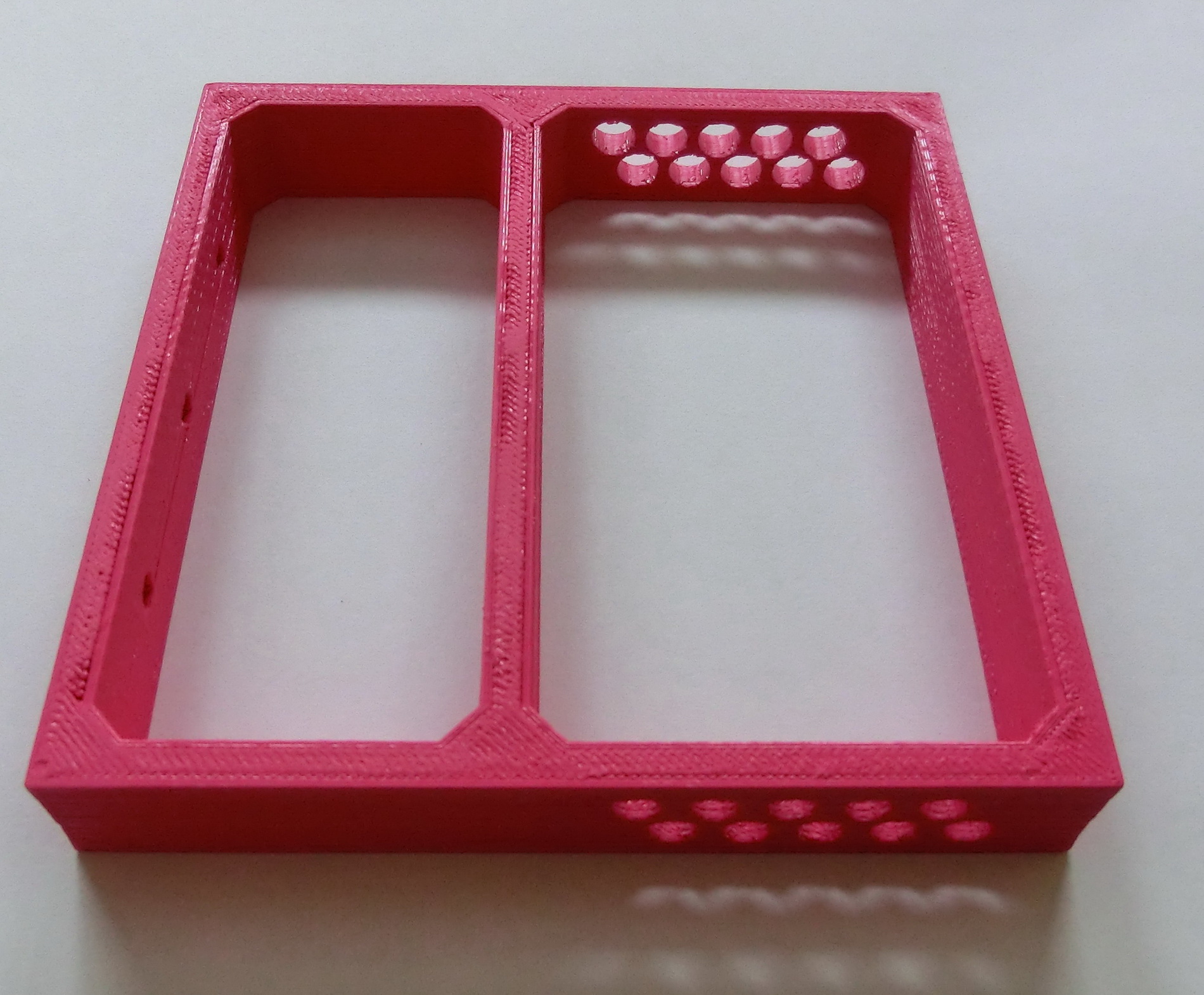
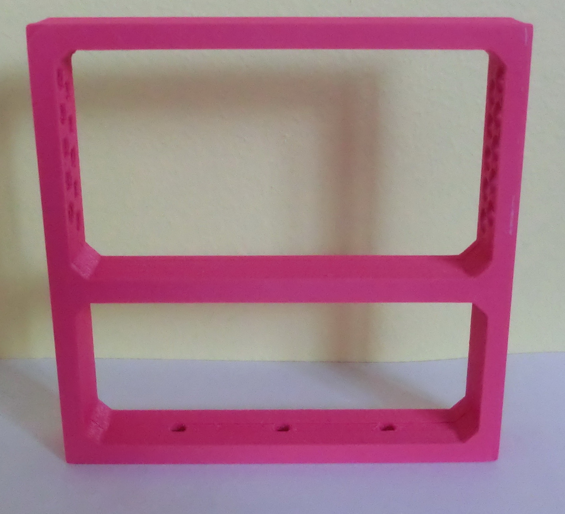
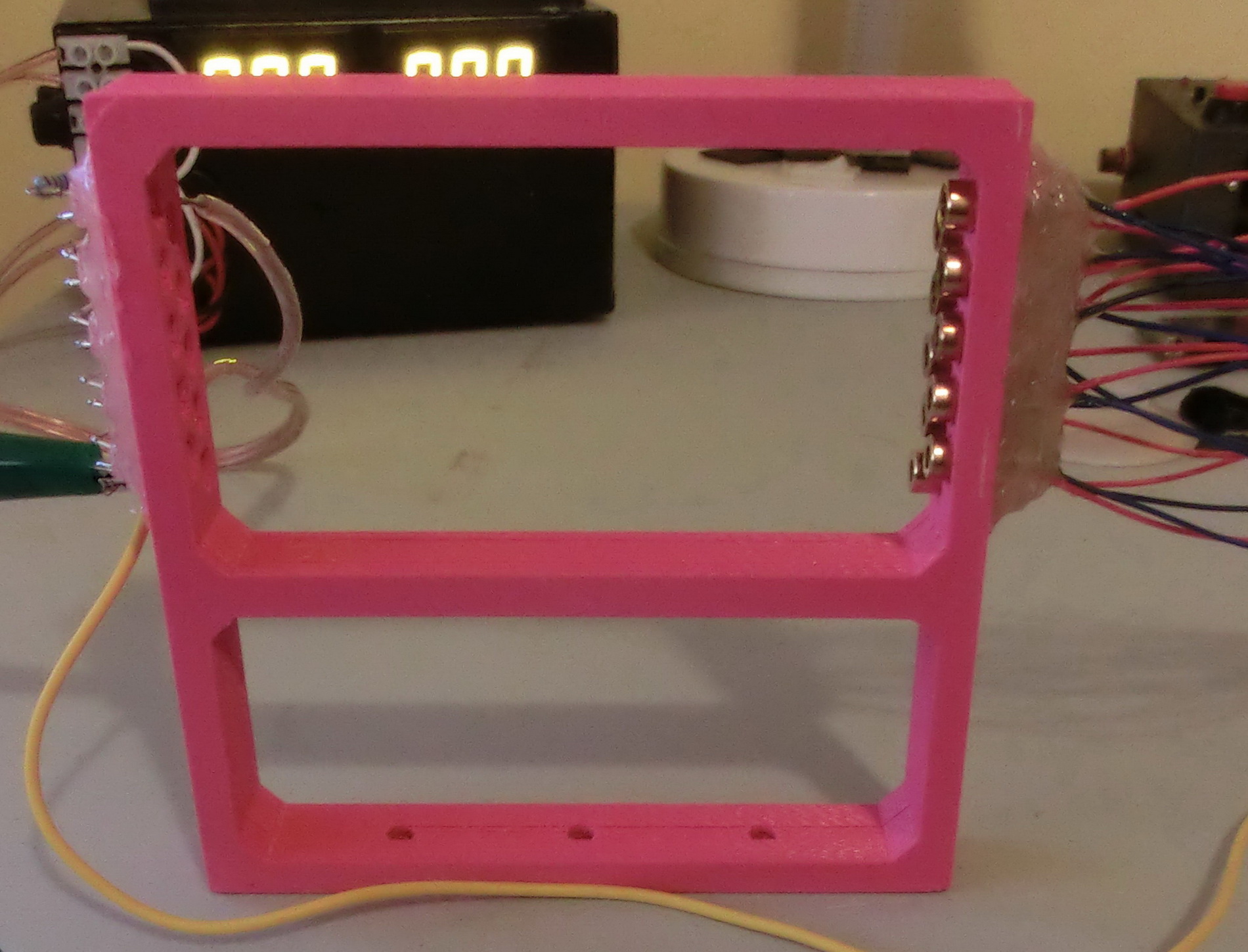
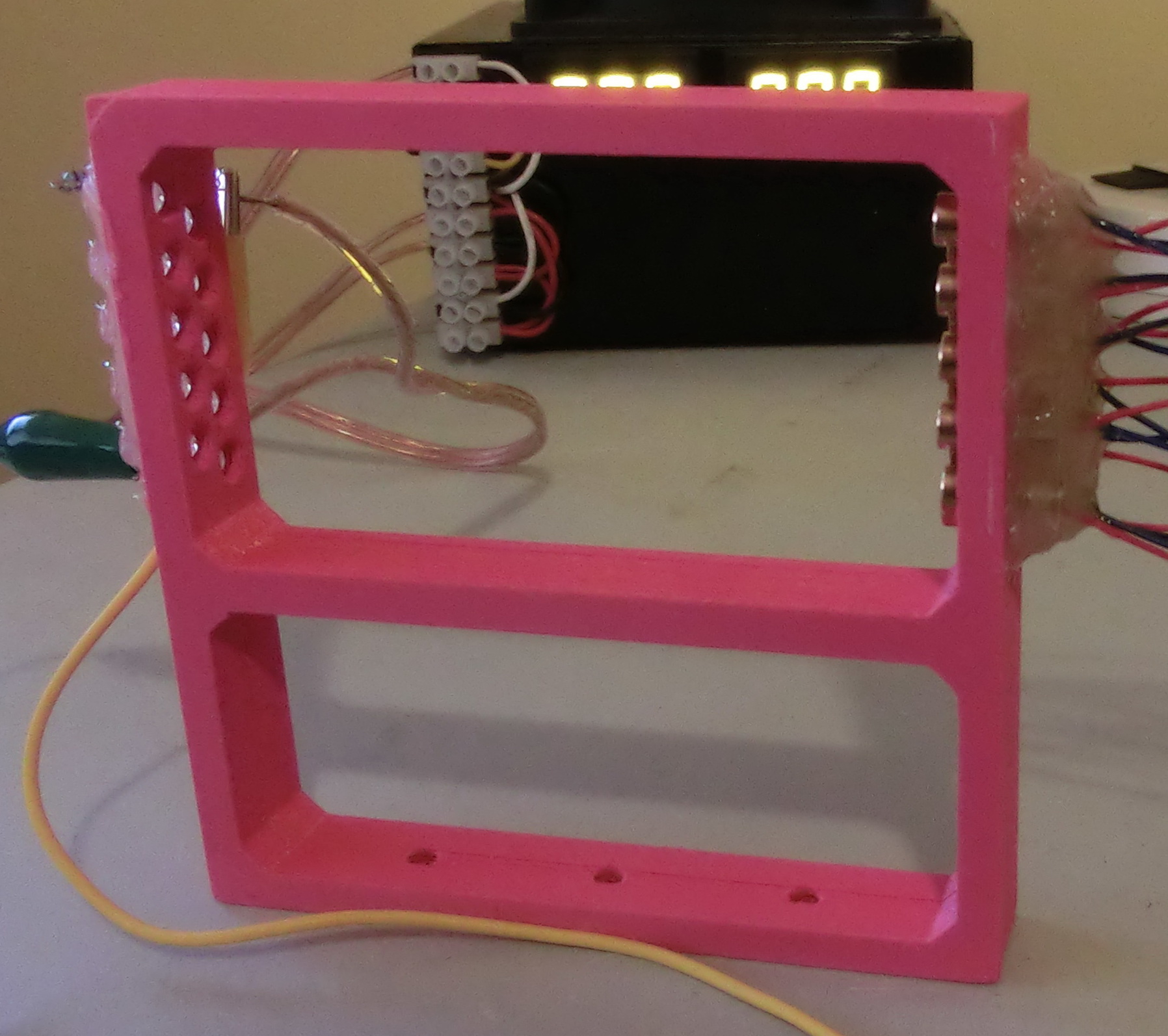
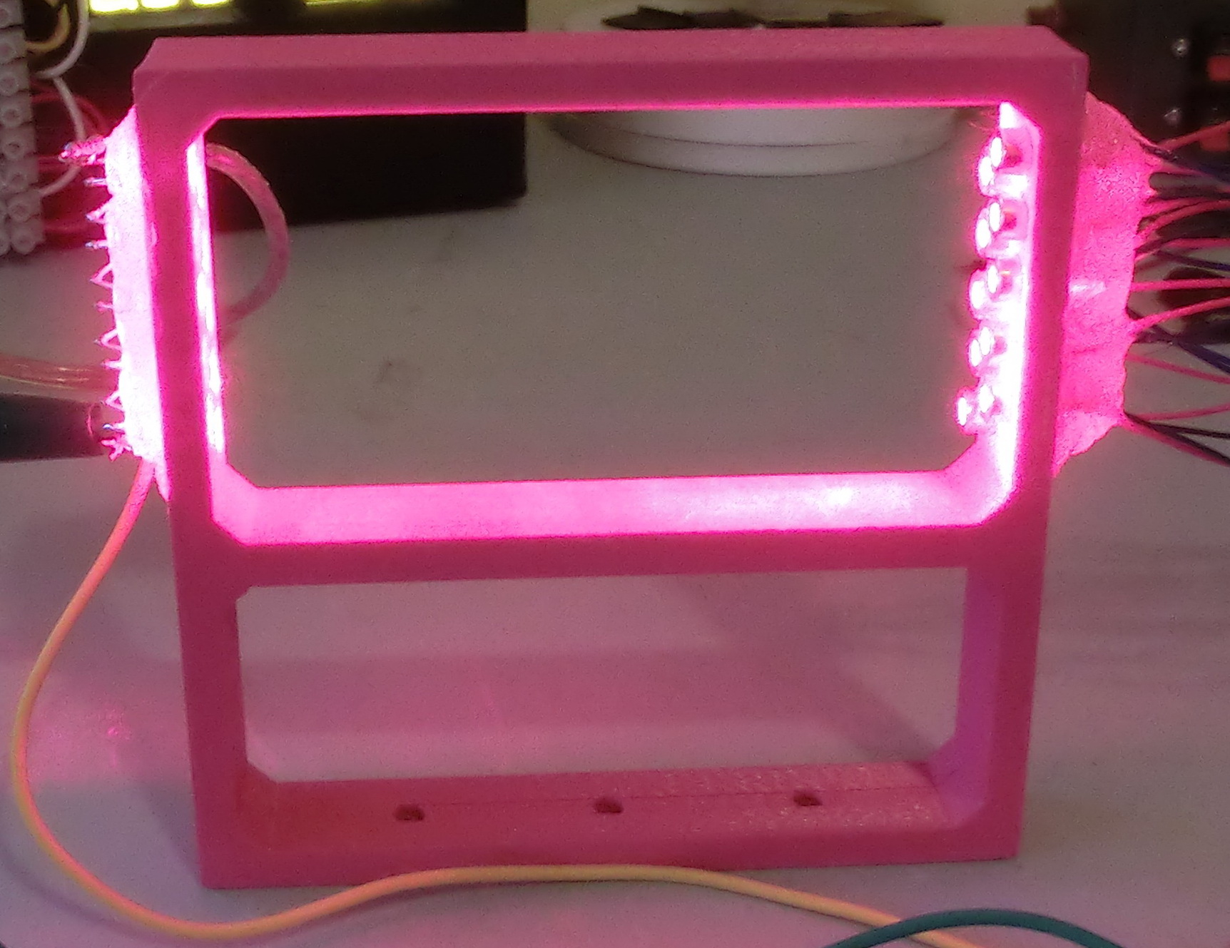
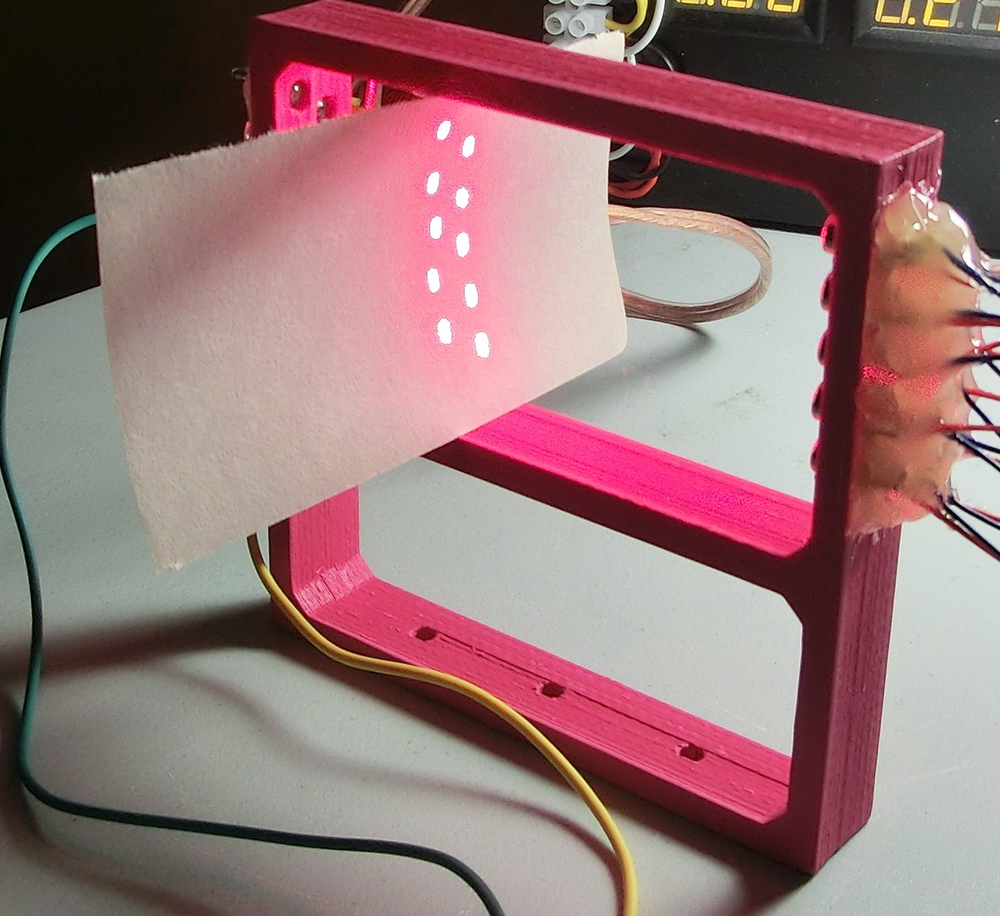
For testing purposes I printed two small frames on my 3D printer and built the laser walls. Because the laser diode casings are larger than the beam I put them in two rows in such an order that there is no space between the beams which guarantees me that even small objects will be detected.
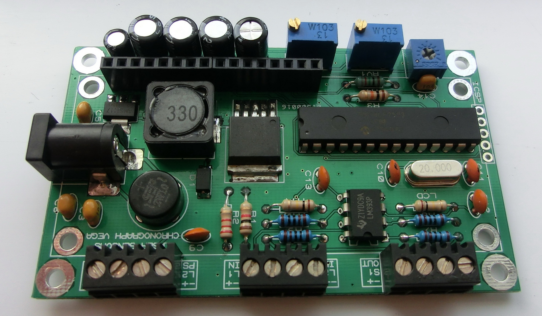
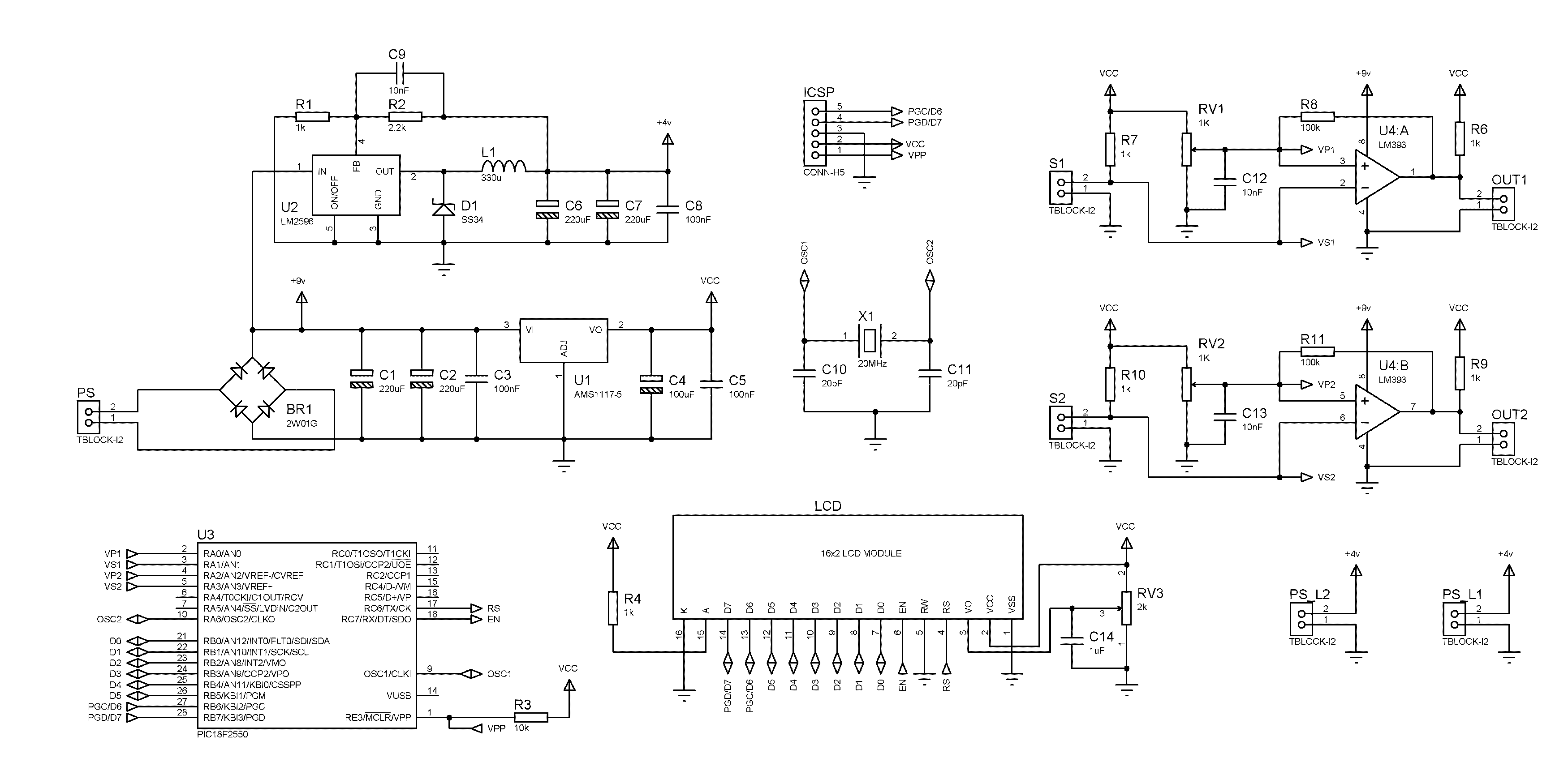
The schematic consists of power supply module and comparators module.
The power supply is high efficiency switching regulator that is set to 4 volts output. The cheap laser diodes found in Interned are rated for 5 volts but there is a current limiting resistor that starts heating quite a lot at 5 volts, so to lower the heat generation in those resistors I set the output to 4 volts.
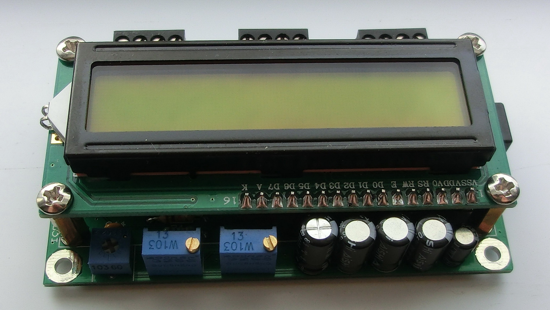
As indicated on the PCB L1PS and L2PS are the outputs for the laser diodes supply. L1 and L2 are the inputs from the photodiodes. S1OUT and S2OUT are the outputs for the impulses that go to the chronograph.
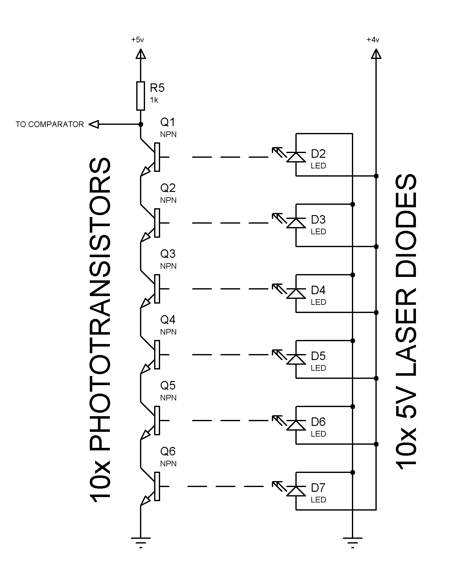
As shown on the drawing further above all phototransistors are connected in series and as long as the laser beam is illuminating them they are open and conducting. In reality they are never fully open and there’s quite a voltage present between Q1 and R5. This voltage is compared by a comparator with an adjustable reference voltage. So when any of the laser beams is interrupted and the corresponding transistor is switched off, the voltage at the point Q1-R5 rises and if it gets above the reference voltage then, the comparator toggles its output. As shown on the schematic RV1 and RV2 are potentiometer dividers that set the reference voltages for the corresponding comparator.
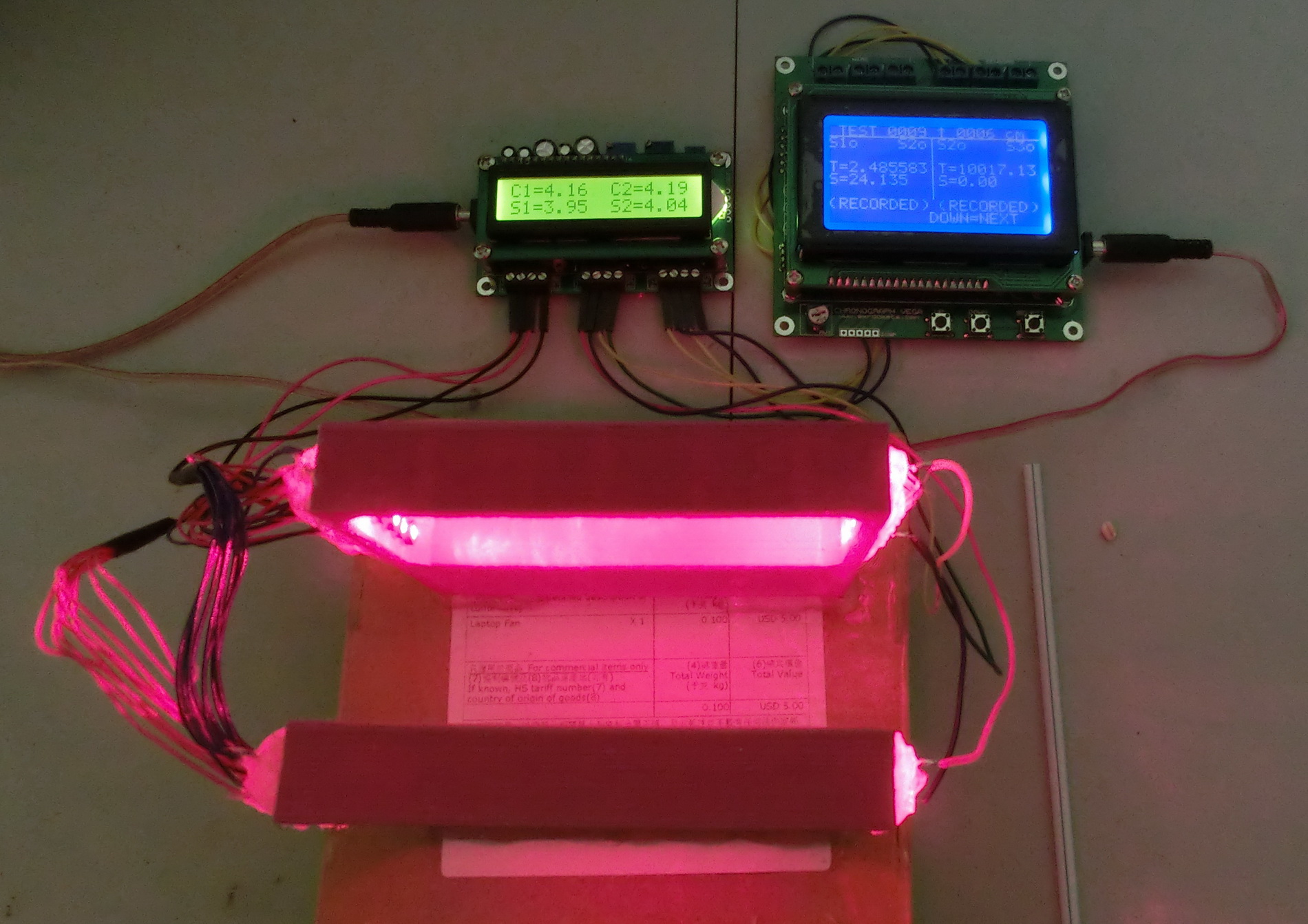
For example in the following test picture I measured the velocity of a grain that was “shot” or blown through a straw. In the picture S1=3.95v is the voltage at point Q1-R5 and therefore I set the comparator reference level C1=4.16v. Respectively for the second sensor the voltage at point Q1-R5 was S2=4.04v and the comparator reference level was C2=4.19v. So when the grain crossed the first wall the voltage at S1 rose briefly above the reference level C1 and this triggered an impulse at the comparator output, which on its turn started the chronograph. The same happened for the second wall when the grain crossed it and this impulse stopped the chronograph.
The measured result is that the grain travelled the 6cm distance between the two walls for 2.485583 milliseconds, which give a velocity of 24.135 m/sec.
Sensitivity – the sensitivity of the system depend on two things.
First, how close are the voltages at point Q1-R5 and the comparator reference voltage. This is to say that the closer is S1 to C1 and S2 to C2 the higher the sensibility because even a partial or short interruption of the laser beam will increase the S1 or S2 voltage above the corresponding comparator voltage.
Second, the sensibility depends on the switching time of the phototransistors – the faster the transistor is switching the higher the sensibility.
This is an important remark because from this depends how large and how fast objects the wall can detect. For example if a very small object flights through the laser beam and only partially disrupts it then the voltage will raise not enough to trigger the comparator. Or if the object is large enough but flying very fast, then the slow switching transistors will switch off only partially and the voltage will not rise above the reference comparator voltage – as a result the comparator will not toggle the output and no impulse will be generated.
LASER_ADD_ON – CADCAM.ZIP
LASER_ADD_ON_FIRMWARE.ZIP
Dear, what is the max speed you find from this project.
The laser diodes were used for measuring bullet velocities.
The chronograph itself was able to measure speeds of 6000 m/s, however with a different trigger system.
Any upgrades to the detection circuit I see you have made laser and wire but that about magnetic field for non ferrous metals