REMOTE CONTROLLED ROCKET LAUNCH FIRING SYSTEM
There are numerous out of the shelf solutions for remote rocket firing however I found that they are either too expensive or lack some futures that I prefer they had, so I decided to make my own. This device is based on the Microchip’s MRF49XA chip and works in the 432-437 MHz band using FSK modulation and additional protocol encryption for higher noise immunity. Also I added some additional circuitry for improved safety.
SPECIFICATIONS:
-4v -16.5v power supply
-30A maximum current – pulse
-12A maximum current – continuous
-Working distance ~200m
-FSK modulation
-Two-way communication – base station and remote control
-8 frequency channels between 432-437 MHz
-LED indication for established RF link
-Audio indication
-4 separated power channels
-Igniter integrity feedback
-Power circuit supply feedback
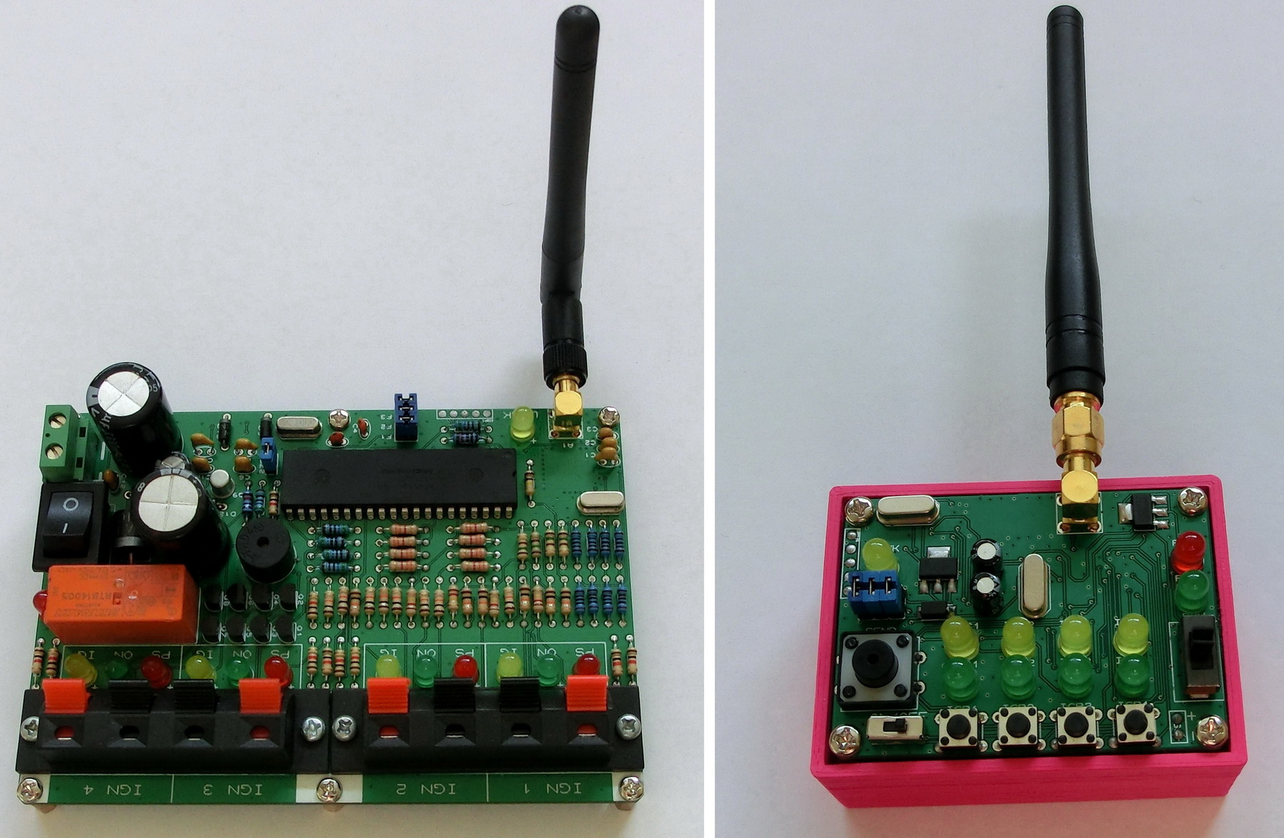
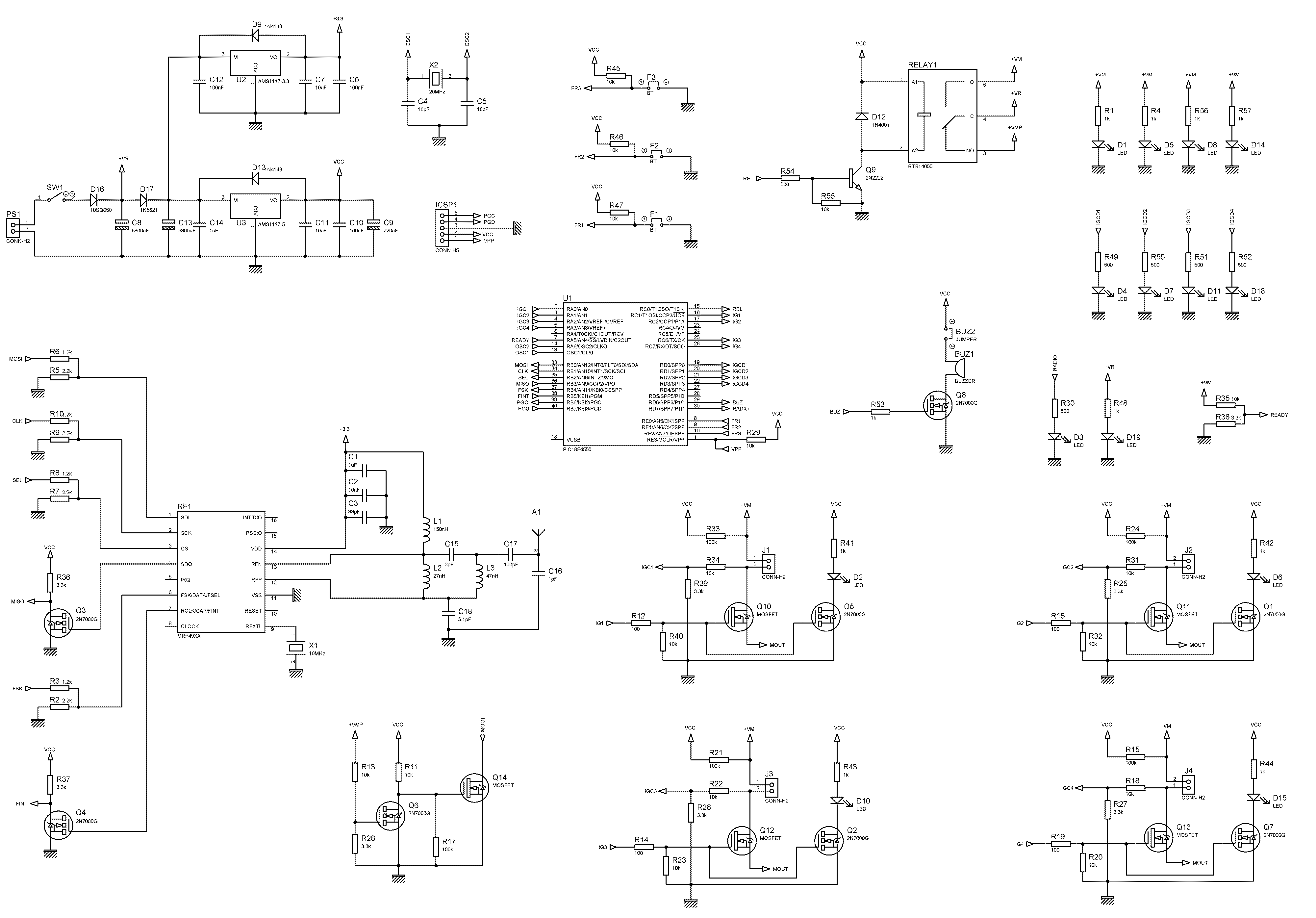
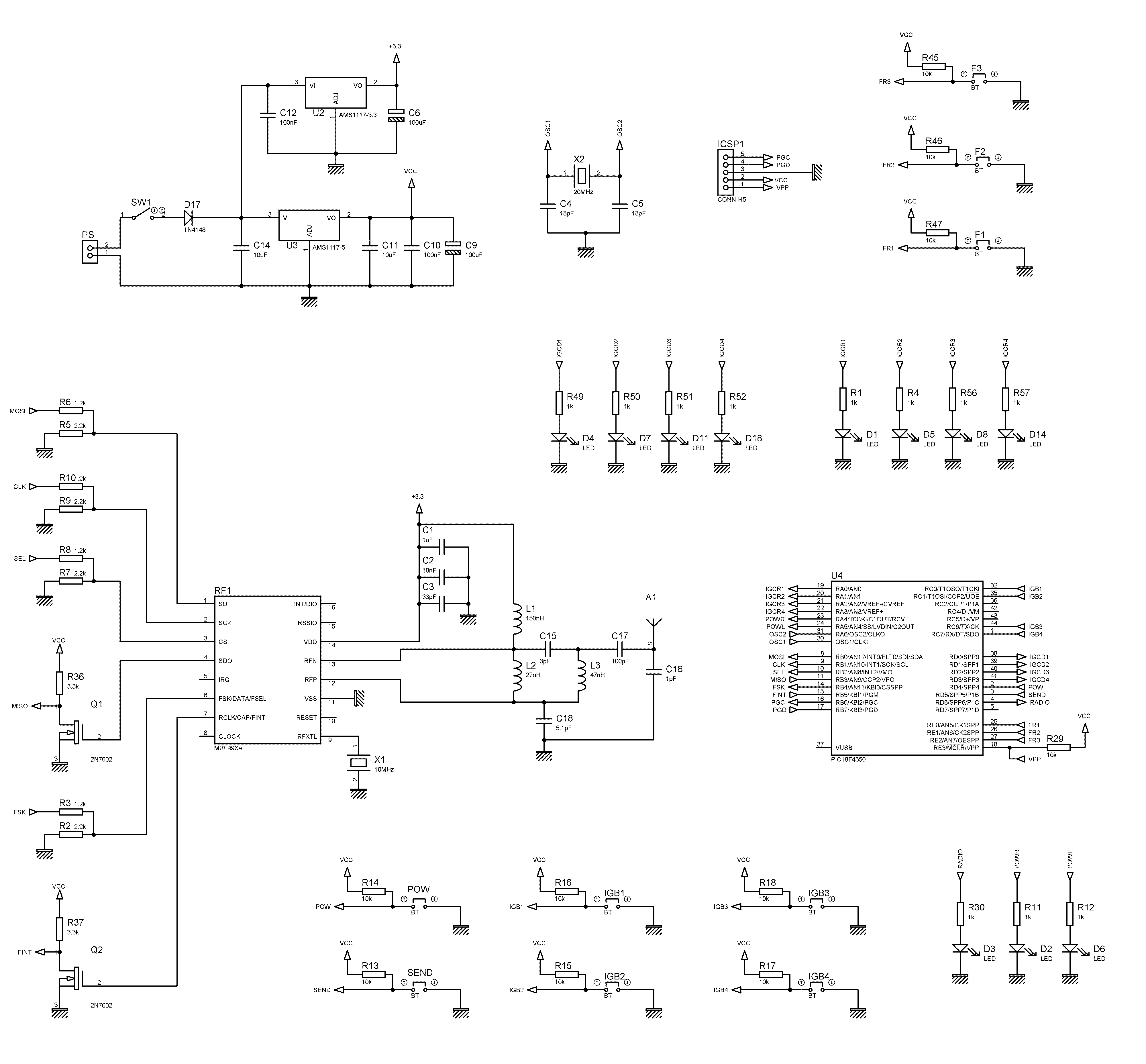
SCHEMATIC BASE STATION SCHEMATIC REMOTE CONTROL
DESCRIPTION:
The REMOTE CONTROLLED ROCKET LAUNCH FIRING SYSTEM consists of two parts – a Base Station (BS) and Remote Control (RC).
There is a two-way communication protocol between both where the RC acts as a Master and the BS acts as Slave. That’s to say the RC constantly sends either “ping” or “command” packets and the BS responds with a “status” packet.
Each command packet can switch on or switch off the main relay to supply power to the ignition circuit. It can also turn on or turn off any of the power MOSFETs thus allowing current to flow through the igniter and launching the rocket.
Each status packet gives feedback whether there is power to ignition circuit (the relay functions correctly), whether the igniter is properly connected and working (igniter integrity) and which power MOSFETs are turned on and off.
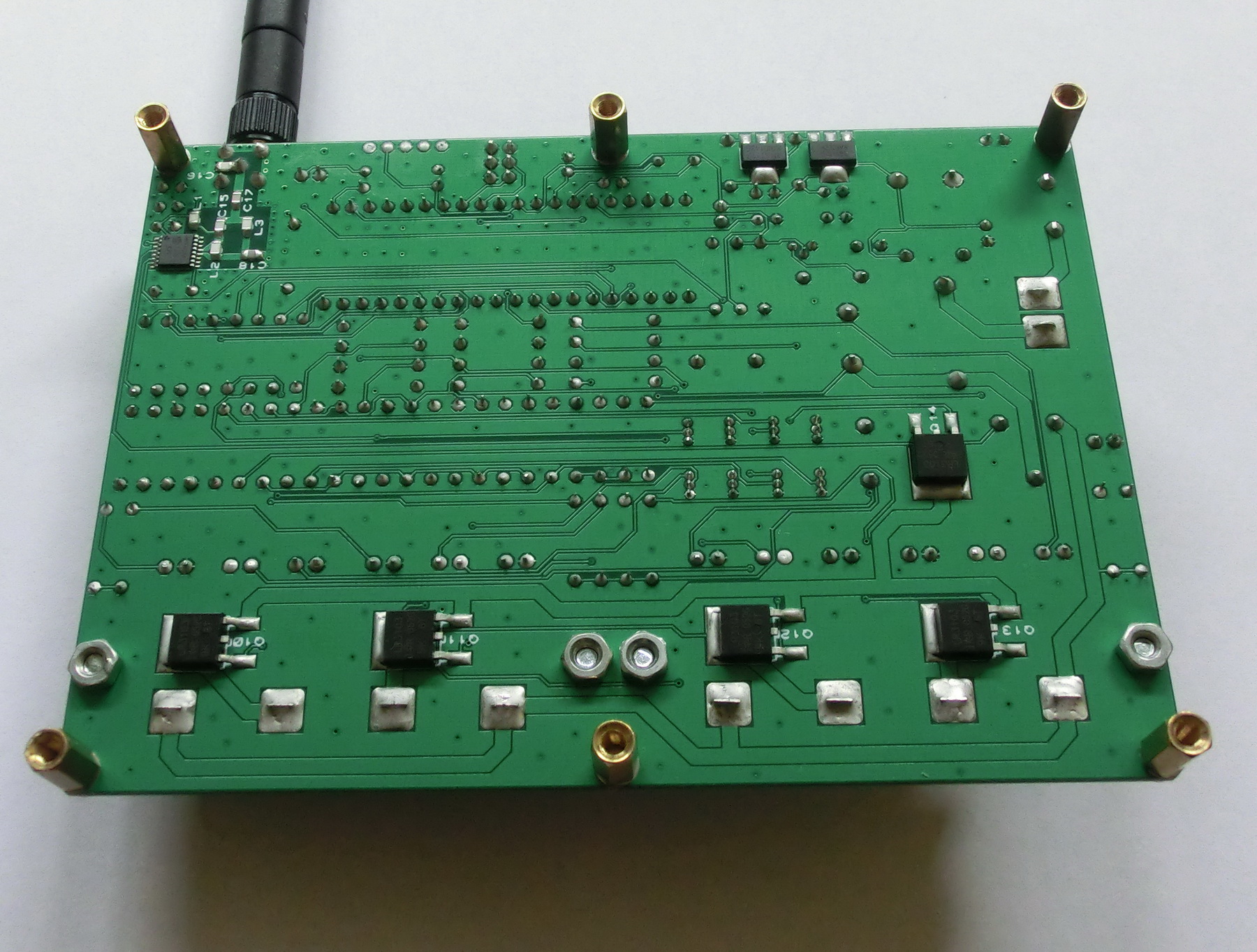
BASE STATION
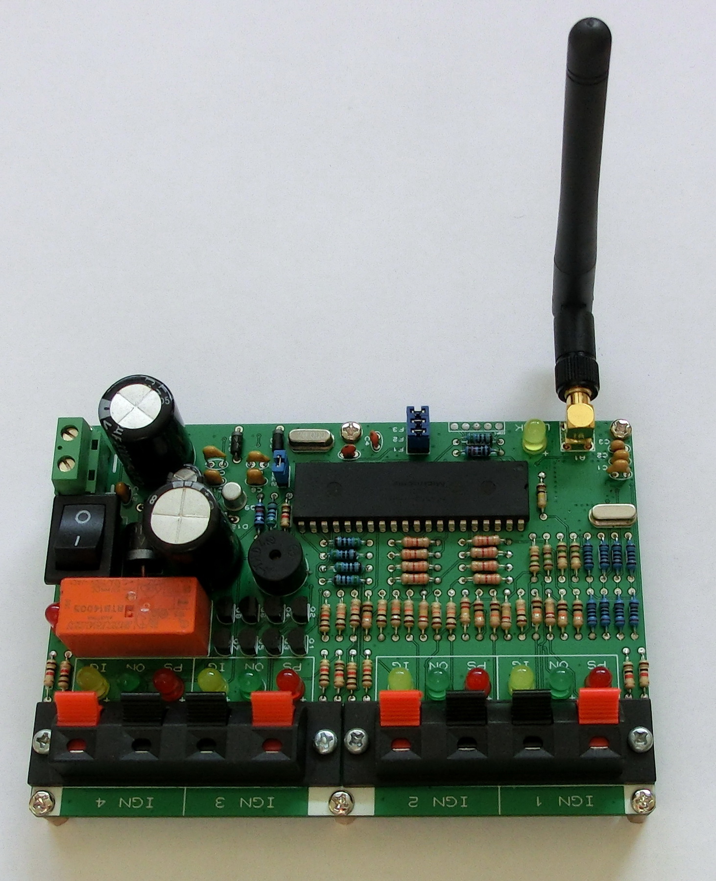
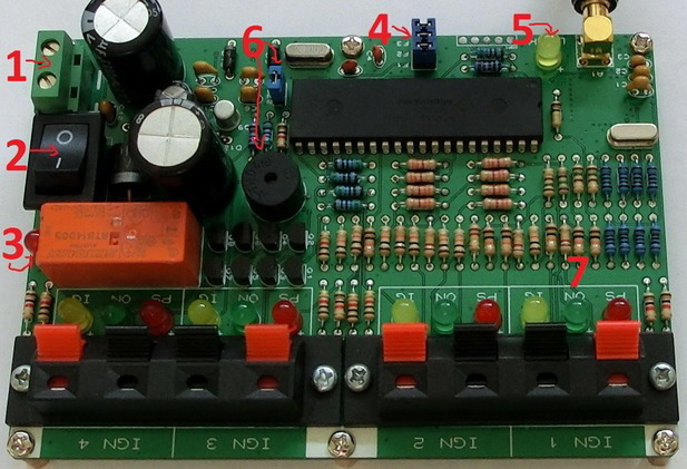
1. Main power supply connector (+ and – are indicated) for both – control and the power circuitry
2. Main on/off switch
3. LED indication for switched on/off power
4. Frequency channel jumpers – there are 8 combinations and F1, F2 and F3 should be the in the same configuration on both devices in order to establish a communication link
5. LINK LED – indication whether a communication has been established between the BS and the RC
6. Buzzer on/off jumper – to turn on or mute the buzzer
7. Four power outputs for igniters – each power output has 3 LED indications:
a) IG LED – Igniter integrity indicator – when the igniter is connected a very small current will flow through it and this current is used to check if the igniter functions properly – if yes, then the LED turns solid on. The igniter feedback circuit has a resistance of 13 kOhm – thus the minimum safety current for the igniter should be:
-680uA – for 9v supply
-900uA – for 12v supply
-1.3mA – for 16.5v supply
b) ON LED – This LED will stay solid on when the power MOSFET is switched on and thus through the igniter will (or can) flow large current – hence the ignition is on.
c) PS LED – This diode is solid on when there is current present on the power circuit I.e. when the relay is switched on and works properly.
*I have a lot of old parts and decided to use them for the base station – that’s why the old classic chunky looks but it can be made a lot smaller using standard SMD components.
REMOTE CONTROL
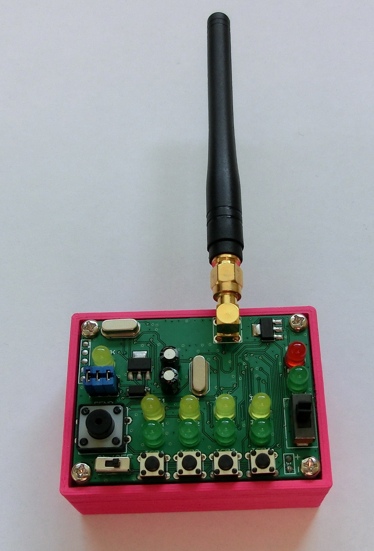
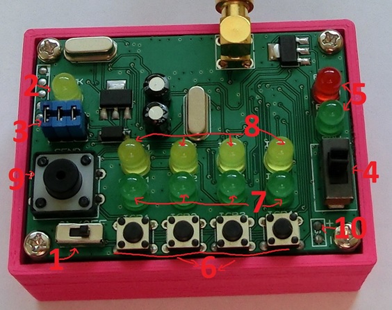
1. Main on/off switch
2. LINK LED – indication whether a communication has been established between the BS and the RC
3. Frequency channel jumpers – there are 8 combinations and F1, F2 and F3 should be the in the same configuration on both devices in order to establish a communication link
4. Relay on/off slide switch – once the desired state of the relay is selected with this switch, the command has to be send by pressing the large button (#9)
5. Relay indication – the green LED indicates the currently selected state of the relay slide switch. The red LED is the feedback from the BS indicating whether there is power present or not to the power circuit
6. Buttons that choose which power outputs will be switched on/off – this command is transmitted by pressing the large button (#9)
7. LEDs that indicate which power outputs will be turned on and off (chosen by pressing buttons 6) by pressing the large button (#9)
8. Igniter integrity indicator feedback LEDs – when the igniter is connected a very small current will flow through it and this current is used to check if the igniter functions properly – if yes, then the LED turns solid on
9. SEND button – by depressing this button, you send the corresponding command
SAFETY – HARDWARE:
For safety reasons there are three separate circuits that have to be switched on in order current to flow through the igniter.
1. RELAY – first this relays has to be switched on (normal position is switched off) in order to supply current to the power circuitry – if it is not, then there is no power going to the igniters.
2. Power MOSFETs – for current to flow through the igniters, these MOSFETs have to be switched on but this is possible only if the relay has been switched before that. These transistors and the relay cannot be switched in the same time.
3. Ground MOSFET – this is an additional power transistor through which all four power MOSFETs are connected to ground. This is an additional precaution in case that any of the four MOSFETs has a malfunction then no current will flow through the igniter unless this transistor is also switched on.
4. Audio indication if the relays is switched on and if any of the power channels is switched on or is to be switched on (see safety-software)
5. The igniter feedback circuit has a resistance of 13 kOhm – thus the minimum safety current for the igniter should be:
-680uA – for 9v supply
-900uA – for 12v supply
-1.3mA – for 16.5v supply
SAFETY – SOFTWARE:
For additional safety there are protocol and procedure rules implemented in the firmware.
1. If the RF link between the RC and the BS is lost, then the relay and the power circuits are automatically switched off.
2. If the relay is switched off, then all power MOSFETs are automatically switched off.
3. 4 seconds delay between the moment when a command to switch on given channel(s) is received and the actual moment when the command is given.
4. If the relay is switched on, the buzzer will give short beeps.
5. If a power channel is to be or is switched on, the buzzer will give a continuous beep.
6. After a given power channel has been enabled, it will automatically switch off after 4 seconds.
SAFETY – RF PROTOCOL:
The RF protocol is software implemented and the main purpose is to give additional noise immunity to the FSK modulation and to prevent random noise to be executed as a command, as well as to slightly increase the communication range.
There is a two-way communication protocol between both where the RC acts as Master and the BS acts as Slave. That’s to say the RC constantly sends either “ping” or “command” packets and the BS responds with a “status” packet. Packets are sent from the Master each 250ms – thus the update rate is 4 per second.
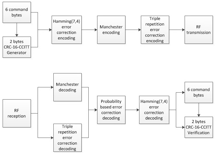
At transmission each packet is encoded in the following order:
-6 command/ping or status bytes + 2 CRC (16-CCITT) bytes
-Hamming (7,4) error correction encoding
-Manchester encoding
-Triple repetition error correction encoding
At reception each packet is decoded in the following order:
-From the Triple repetition encoding and the Manchester encoding, each bit in the six bytes is corrected and extracted based on “soft” probability based method.
-Manchester decoding
-Error correction based on the Hamming(7,4) decoding
-The 6 command/ping or status bytes + 2 CRC (16-CCITT) bytes are extracted
-From the 6 command/ping or status bytes new 2 CRC (16-CCITT) bytes are computed
i. If the received and the computed 2 CRC (16-CCITT) bytes are equal then the 6 command/ping or status bytes are considered valid
ii. If the received and the computed 2 CRC (16-CCITT) bytes are not equal then the 6 command/ping or status bytes are considered invalid and discarded
By using this protocol I wouldn’t say that it is impossible for random noise to be considered as a false command but the probability for that is very low.
HOW TO USE:
1. Connect the igniters to the BS
2. Turn on the power supply on both BS and RC
3. Check if the link is established
4. From the RC select to switch on (slide switch) the relay
5. Send the command to switch the relay
6. The buzzer start beeping slowly
7. Check the feedback LED on the RC that there is power to the power circuits
8. Select which channel is to be turned on using the buttons
9. Send the command to turn on the selected power channels
10. The buzzer start beeping continuously for 4 seconds *
11. 4 seconds later the selected power channels are enabled
12. Another 4 seconds later all power channels are disabled and the buzzer returns to beeping slowly indicating that the relay is still switched on
*You can cancel this from the RC command by:
-switching off the relay
-switching off the power supply
-deselecting all channels and sending another command
BASE STATION PCB FILES
BASE STATION FIRMWARE
REMOTE CONTROL PCB FILES
REMOTE CONTROL FIRMWARE
Leave a Reply