After I some time I found free moments to finish an old project – a flight computer with programmable outputs. This flight computer is based on my small digital barometric altimeter and the small accelerometer.
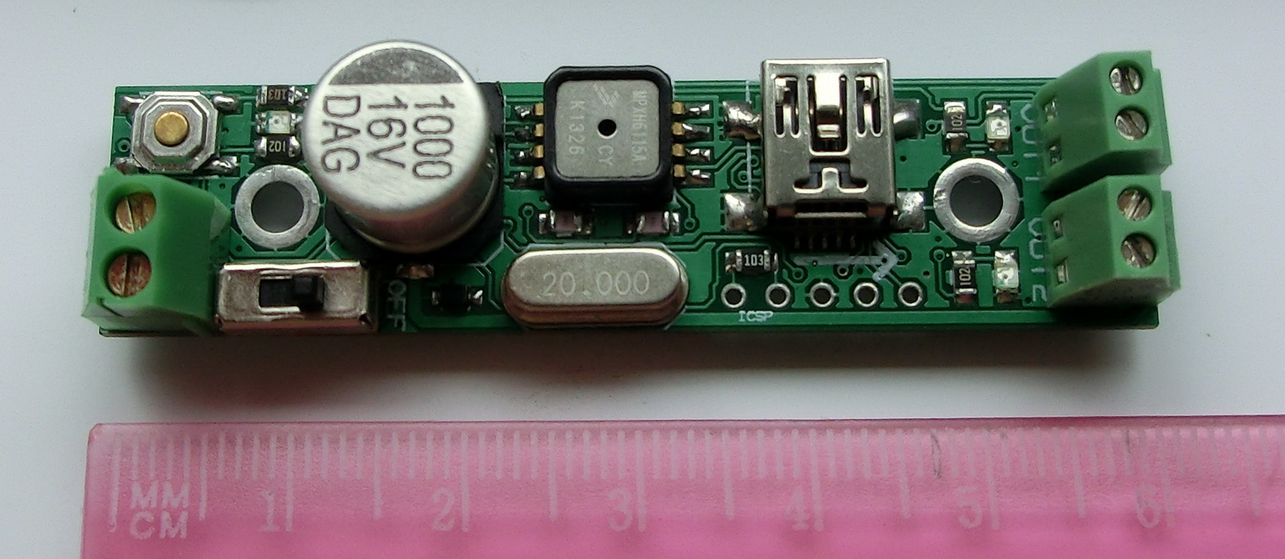
 Despite the modest dimensions of the device – only 60x15x15 millimeters – it has excellent functionality. The main characteristics are:
– Barometric altitude measurement up to 18km
– High g acceleration sensor
– 40 samples per second / 13 bit ADC
– 3.5 minutes recording time
– Igniters connectivity check for both channels (LEDs for each channel will show the status of the igniter)
– USB connection
– 7.5 to 16 VDC power supply with on-board ON-OFF switch
– 10A (40A pulse) MOSFET for each channel
– Selectable on-time for each channel (between 0.1 and 5 seconds)
– Each channel has igniter connectivity feedback for back-up purposes (one channel can substitute the other in case a defective igniter is detected during flight)
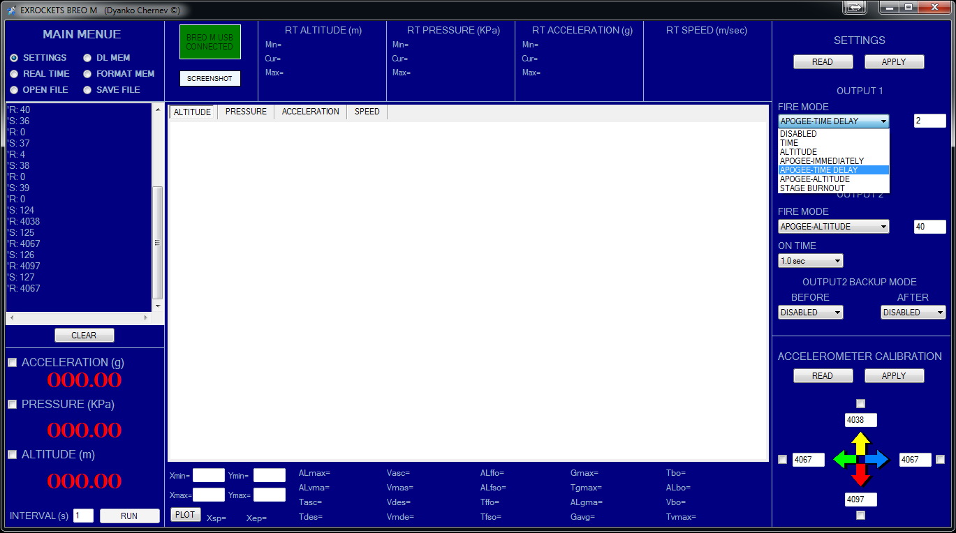
– 2 individually programmable outputs where each output can be set up for one of the following events:
1.DISABLED – Output won’t fire
2.TIME – Fire after the time elapsed (in seconds)
3.ALTITUDE – Fire as soon as the predetermined altitude is reached (in meters)
4.APOGEE-IMMEDIATELY – Fire at apogee
5.APOGEE-TIME DELAY – Fire n seconds after apogee
6.APOGEE-ALTITUDE – Fire at a predetermined altitude after the apogee has been reached (in meters)
7.STAGE BURNOUT – Fire as soon as the initial acceleration falls below 1 (motor burnout)
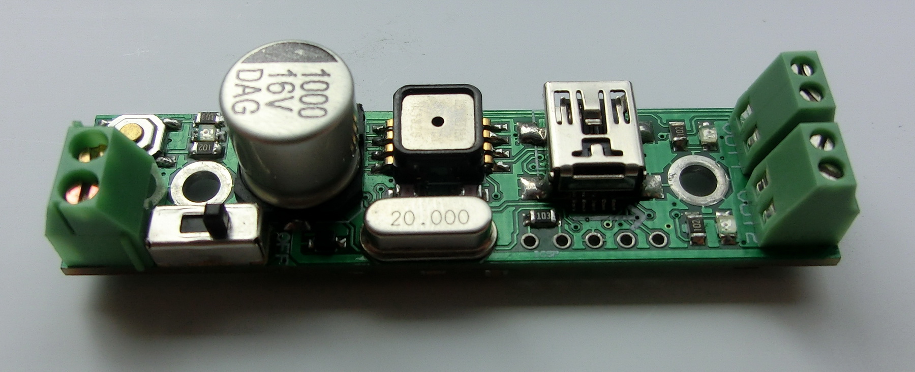
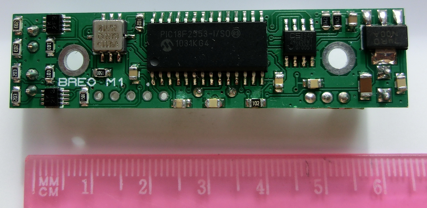
I have given it a good thought how to miniaturize the flight computer while keeping the assembly relatively easy for a DIY project and the only way to do that was by using miniature MOSFET transistors which are a bit tricky for soldering but not that hard at all.
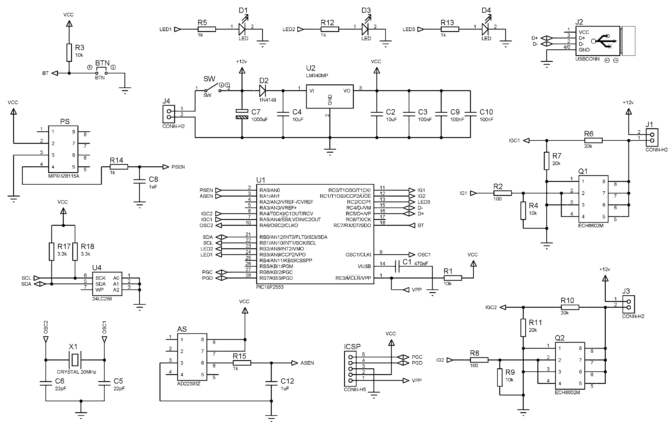
And the schematic for my flight computer:
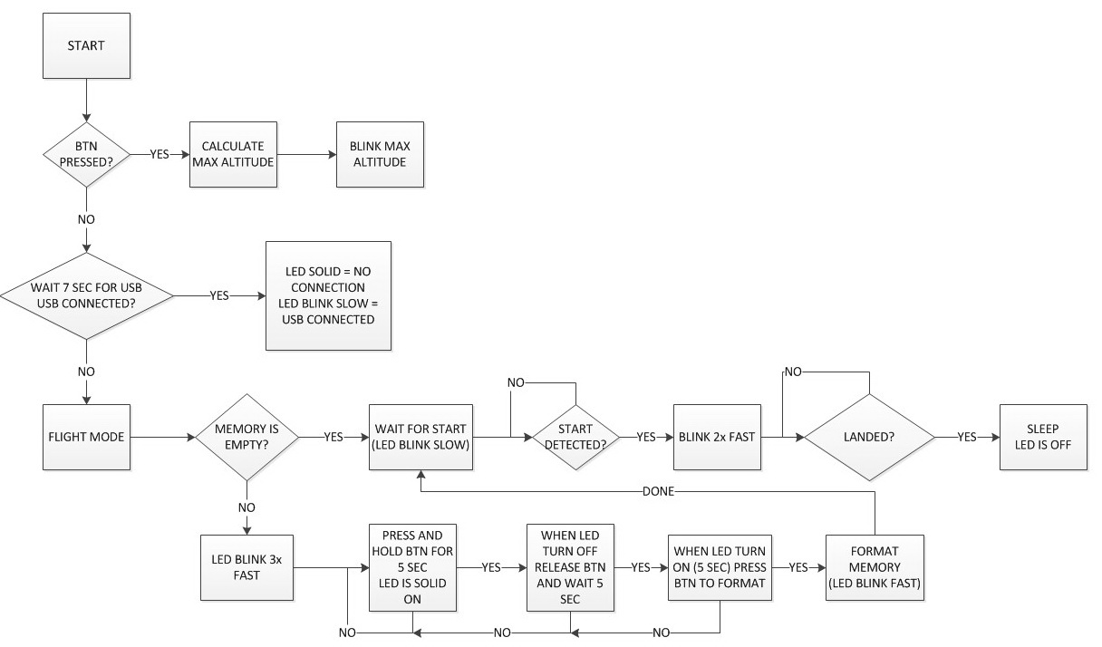
Once I finished soldering the board I started writing the firmware which has basically three main parts – USB part, on-the-field maximum altitude calculation and the flight mode.
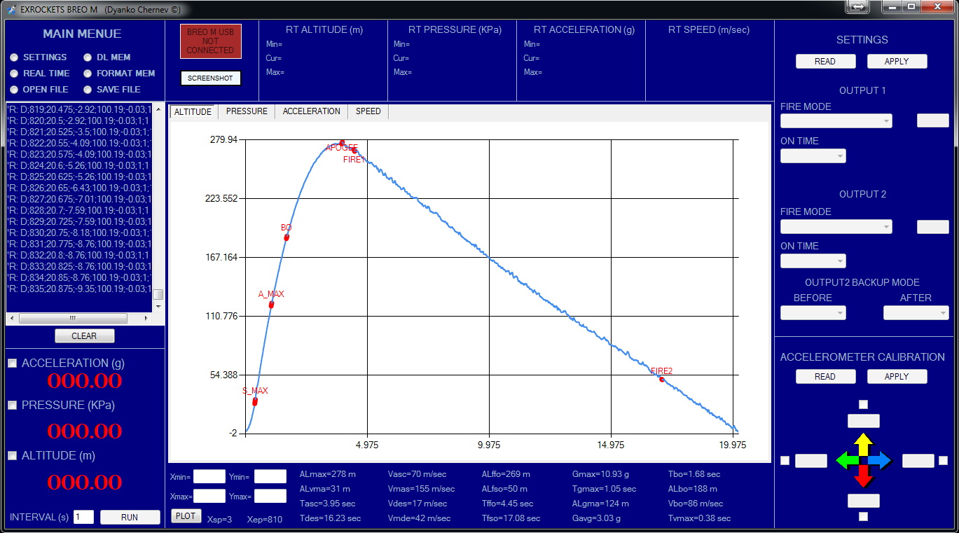
Then the next part was to write a suitable desktop application for the USB communication part, here I appreciate Sergey’s excellent suggestions how to better organize the functionality.
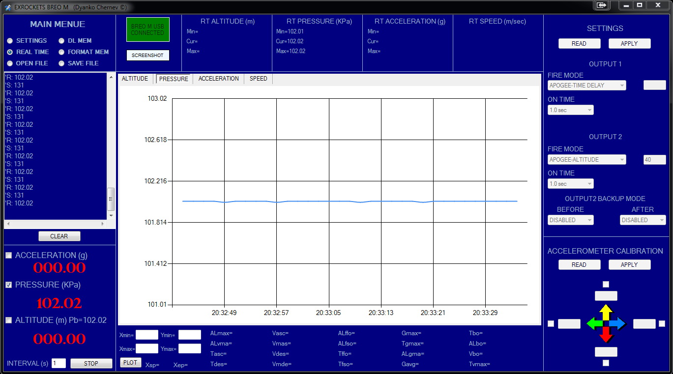
The flight computer passed so far the testing in my improvised barometric chamber and I hope soon to be tested in a real flight.
UPDATE:
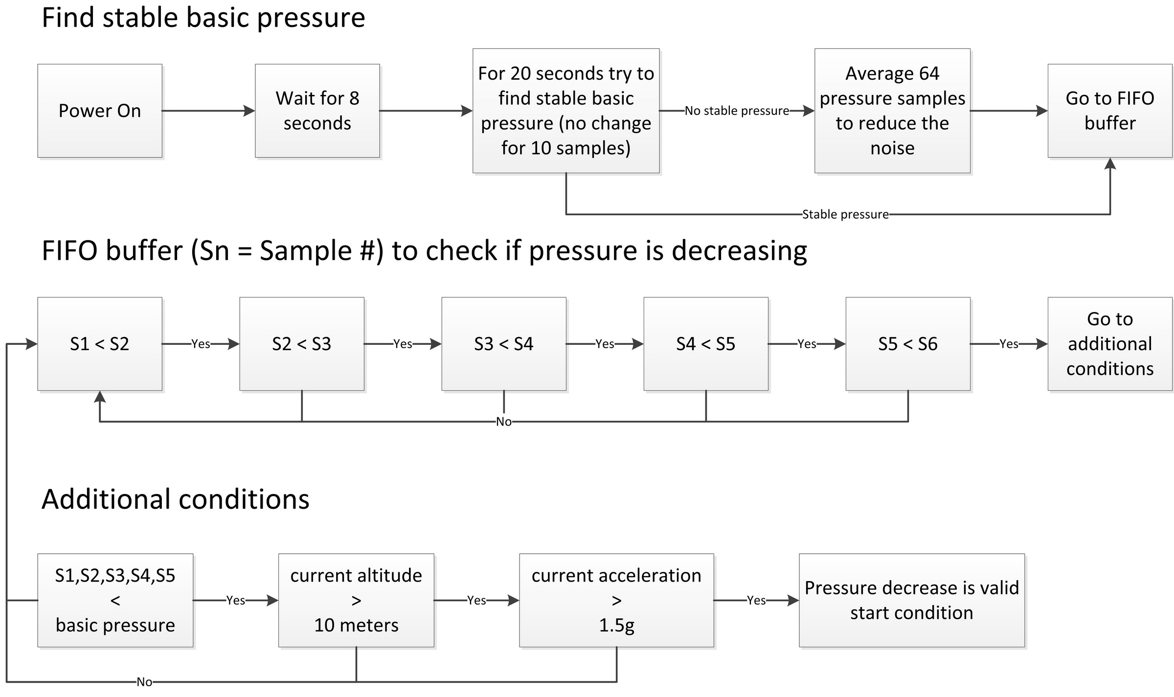
RocKI (http://kia-soft.narod.ru) mentioned a situation where a false start condition could trigger the flight computer. As a result the computer could be fooled and the ejection charge could be fired untimely. This situation arises when the electronic bay is tidily closed and the next bay is mounted on the top by pressing it down. This acts much like a piston and temporarily increases the pressure in the electronics bay. As soon as the pressure starts falling down to equalize with the surrounding pressure and if this is combined with a strong shaking of the rocket, then the start detecting algorithm will be fooled that the rocket is launched.
To avoid this problem I made some modifications in the firmware start detection algorithm – now it is much harder to have a faulty start triggering. However as a result of the new algorithm you should allow about 30 seconds between switching on the flight computer and launching the rocket. This time is necessary for the flight computer to make some additional calculations. Launching before those 30 seconds have elapsed could result in faulty initial calculations and this could have detrimental consequences.
Hello! Where can I order this on-board computer or do you make them on order?
How much?
With best wishes,
Igor
Hello Igor,
this is not a commercial project but the design and the software are free to use. If you are interested in the project, please send me a message through the contacts form.
Regards