One thing is for sure – rockets always come back to the ground, however sometimes we are not sure where they landed. Currently there are many tracking devices on the market, but they are either too expensive, too bulky or require special radio equipment which is often not available to everyone.
So started this project with the hope to make a rocket tracking device that is: light, easy to operate, inexpensive, has an extended range and available to everyone. After giving some thought how can I achieve this I came with following idea for an FM tracking device.
THE IDEA:
Tracking an FM signal requires specialized equipment and can be challenging, but that is what I want to avoid. So I think that this would require more logical than technical approach in solving the problem.
My idea is to transmit a tracking audio signal (simple beeps) on the FM radio band with stable and predetermined frequency while varying the power. The audio signal will be in the same time an identifier for which power level it is transmitting at the moment.
For example the microcontroller will generate one beep and will switch off the attenuators for full power transmission. Then 20 seconds later it will generate two beeps and switch one of the attenuators on for transmission at “full power less 10db”. Another 20 seconds later it will generate three beeps and switch the both attenuators on for transmission at “full power less 20db). Finally, after another 20 seconds and it will beep with the piezo buzzer.
So even with a simple FM radio(s), when we have a stable and know transmitting frequency that varies by power and each level of transmitting power is identified, we can form a searching grid by simply observing the presence/absence or the quality of the receiving signal until we finally hear the buzzer.
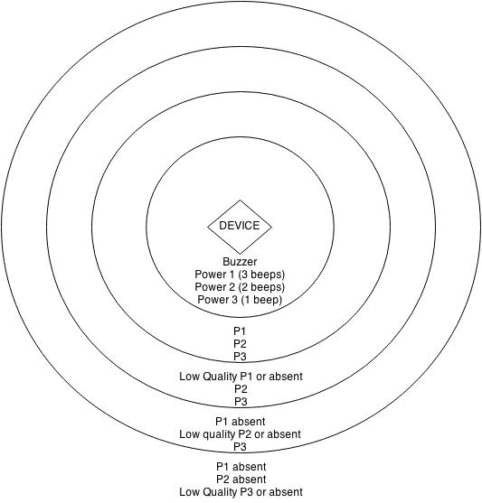
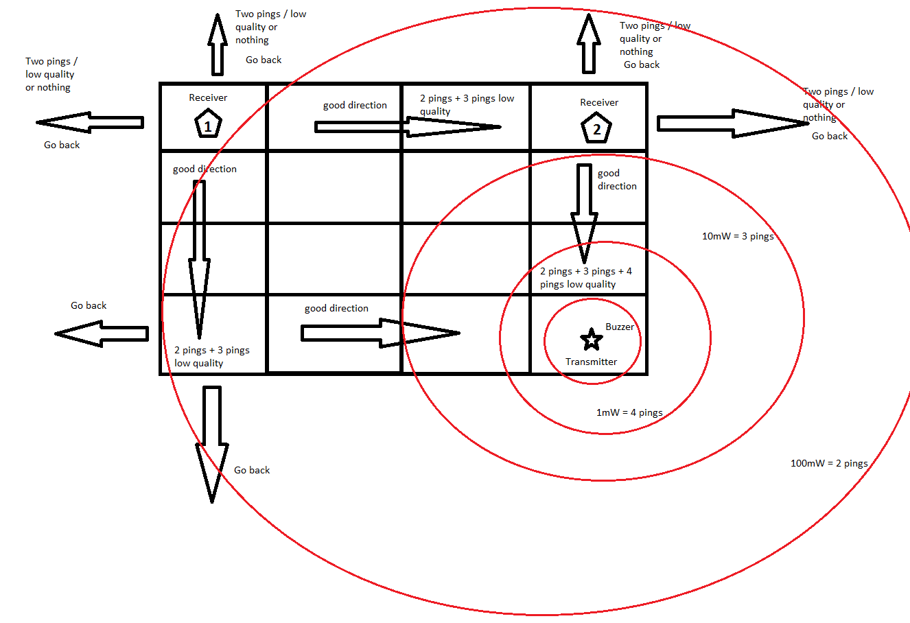
In reality, things are quite different – the receiving area is not a circle and depends on both- the transmitting and the receiving antenna position and terrain. So a directional antenna and FM radio with power meter (witch of some sort the most radios nowadays have) could be very practical but not mandatory in order to form a meaningful search grid. Handheld or car GPS in pedestrian mode can be very helpful to form and follow the grid. An example of the search grid:
DESCRIPTION:
![]()
The microcontroller generates the audio signal that will be fed to the FM modulator and controls the attenuators and the buzzers.
My knowledge in the analog domain is very limited and I decided that it will be impractical, not to say impossible, for me to make stable FM modulator, therefore I decided to use an FM chip that will take care of this problem and will not require adjustable coil inductors. After some research I found that the BH1417F will provide me selectable and in the same time very stable frequency. This chip is much more than what I will be using it for but it can be found on Ebay for 3$, so it doesn’t really matter. The FM signal is then coupled to the power amplifier MMG3007, which provides a good range at full power. It can be directly replaced with other more powerful amplifiers if I have to.
After the power amplifier I have two digitally controlled attenuators which have two states – on and off. In on state each one will reduce output power to the antenna by 10 db, where in off state they will put the signal through with no power attenuation.
Finally, there is strong piezo buzzer on-board that can be heard from a couple of meters even in open space.
So here’s how the schematic look like…
![]()
There are 3 small LEDs that will indicate when and at what power level it is transmitting.
JP5 is used to disconnect the power to the Buzzer in case it’s not needed.
C16* is optional – you need it in case you want to be using the higher frequency band (106.7-107.9 MHz)
L1 and L2 are chip inductors, where L2 can be replaced by one with lower inductance or simply with 0 Ohm resistor.
MMG3007 is a power amplifier with a fixed gain of 20 dBm and can be replaced with another power amplifier working at 5v having the same footprint. I used ADL5602. This amplifier draws about 90 mA current and provides about 100 mW transmitting power. If you want to limit the power output you can replace L2 with one 33 Ohm resistor that will limit the current drawn by the PA. In case you want to increase the transmitting power you can use another amplifier with higher gain, but it will draw more current of course.
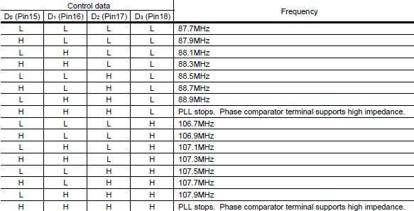
JP1, JP2, JP3 and JP4 will select the transmitting frequency according the following table:
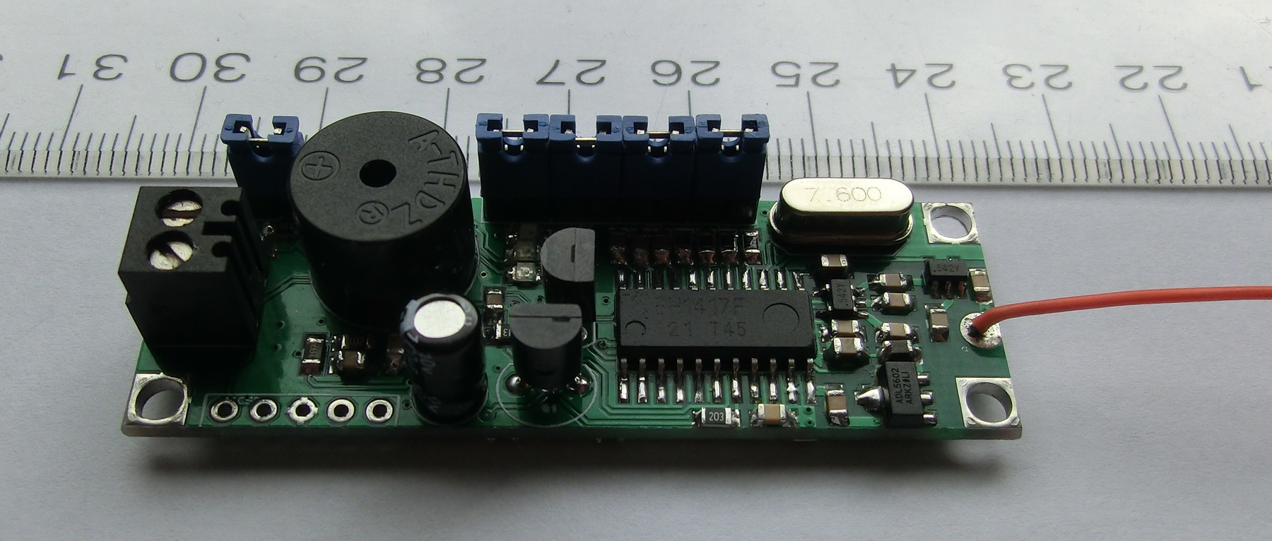
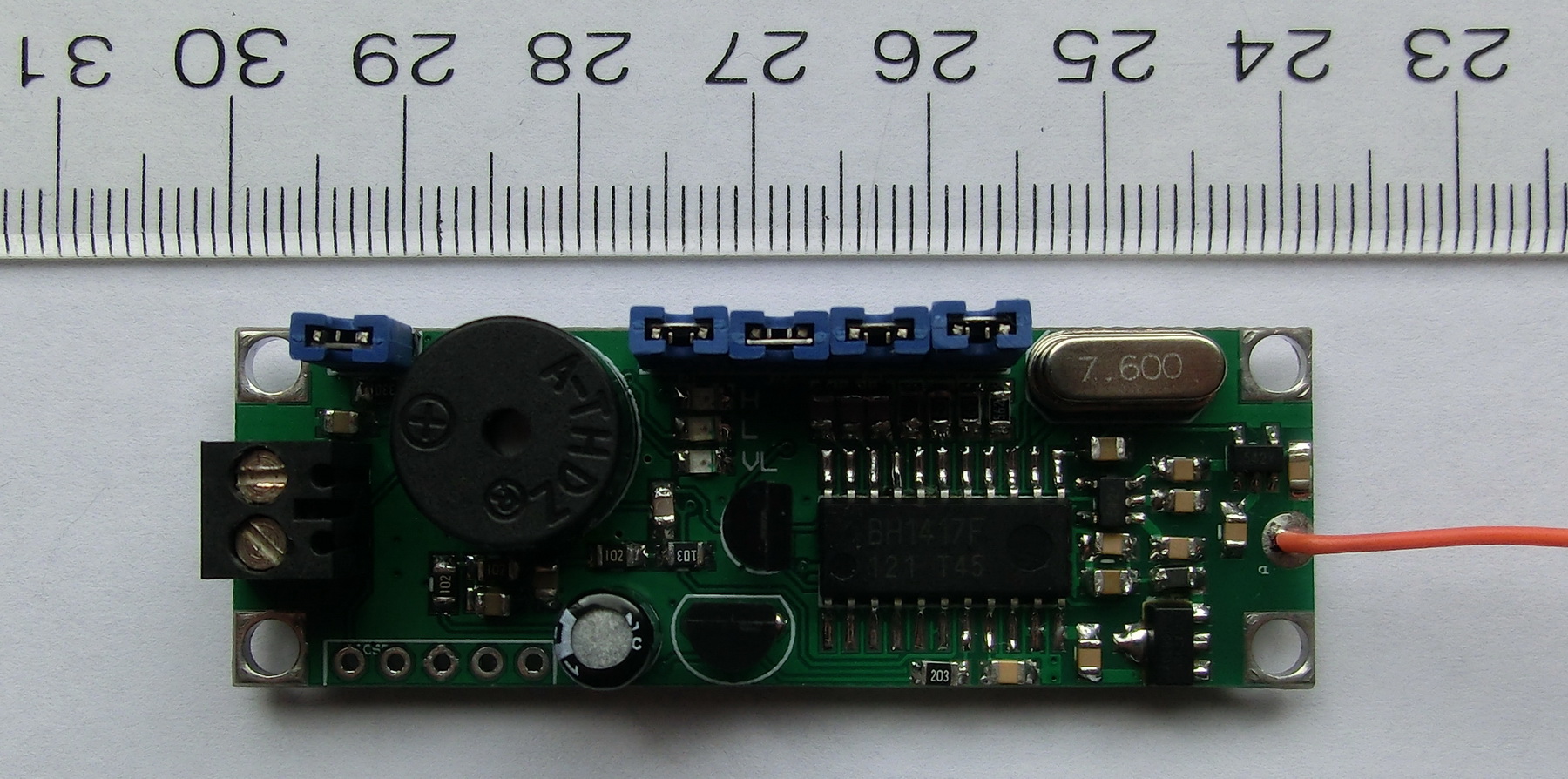
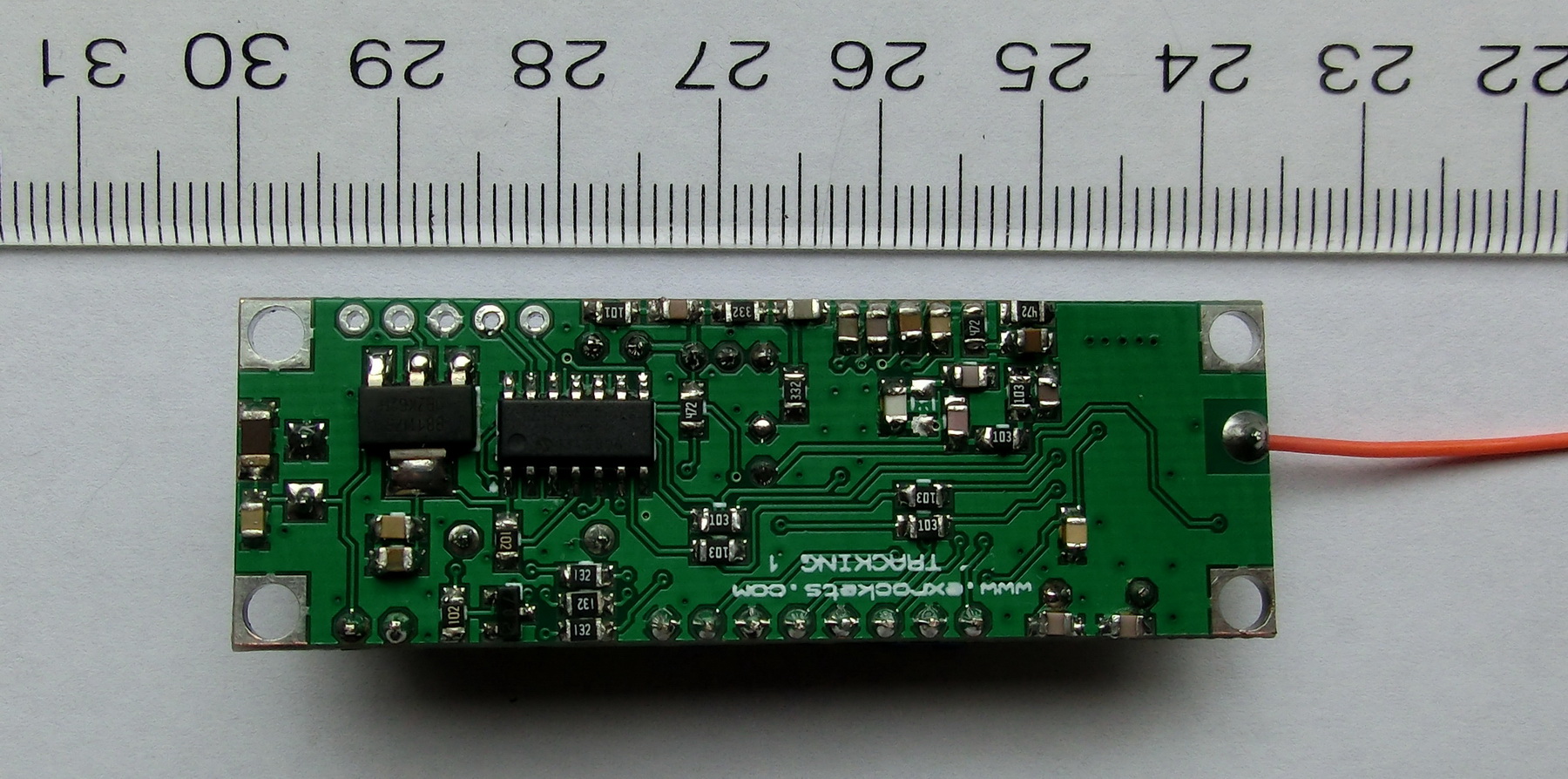
The next step was to draw and order the actual PCB. Drawing the HF part of the PCB required some additional precautions but everything worked fine and the PCB has very reasonable dimensions 60×20 mm.
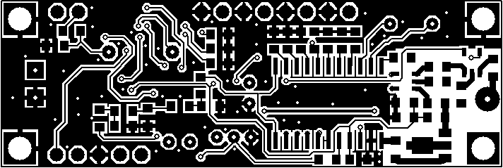
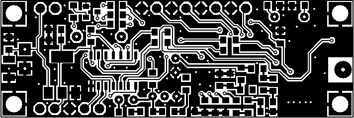
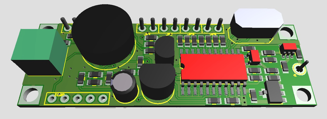
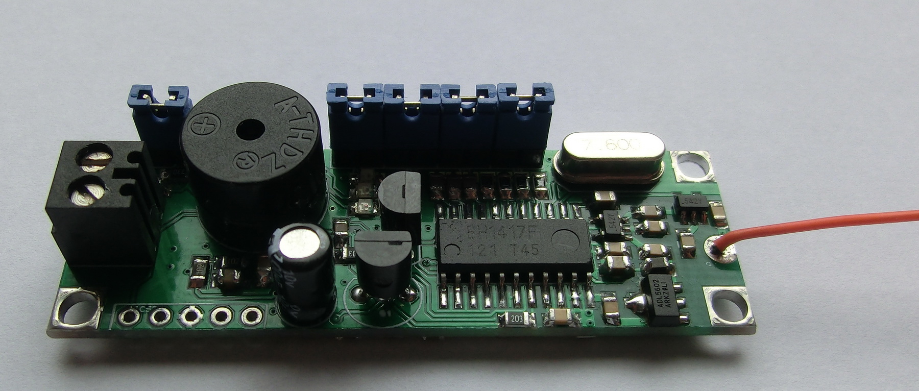
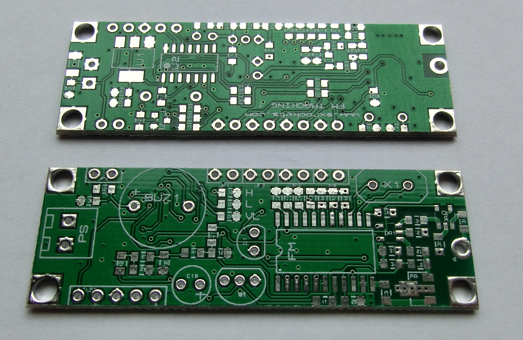
Finally the manufactured PCBs looked very good and I immediately started my favorite part – soldering the board, with all parts on it weights only 11 grams. This is how the real PCB and transmitter look.
So far I tested the transmitter around the house and my first impression is very optimistic. This transmitter immediately locks the frequency. The frequency is stable and corresponds to the values mentioned in the table also the band is narrow – about 100 KHz around the center. The current consumption is about 115 mA which is expected (the power amplifier is rated 85 mA, the FM chip is about 20 mA and the micro controller draws another 10 mA).
Next step is to test the transmitting range and how easy/hard is to find it in the field.
N.B. This transmitter exceeds the maximum allowed power output for home devices in the 87-107MHz band. So if you test it at home, make sure you select a frequency that will not interfere with any local FM station. Of course we usually launch our rockets far from any inhabited areas so this won’t be much of a problem there but still it is best to choose unoccupied frequencies.
PCB Manufacturing Files (Gerber output)
MCU Firmware (hex format)
Leave a Reply