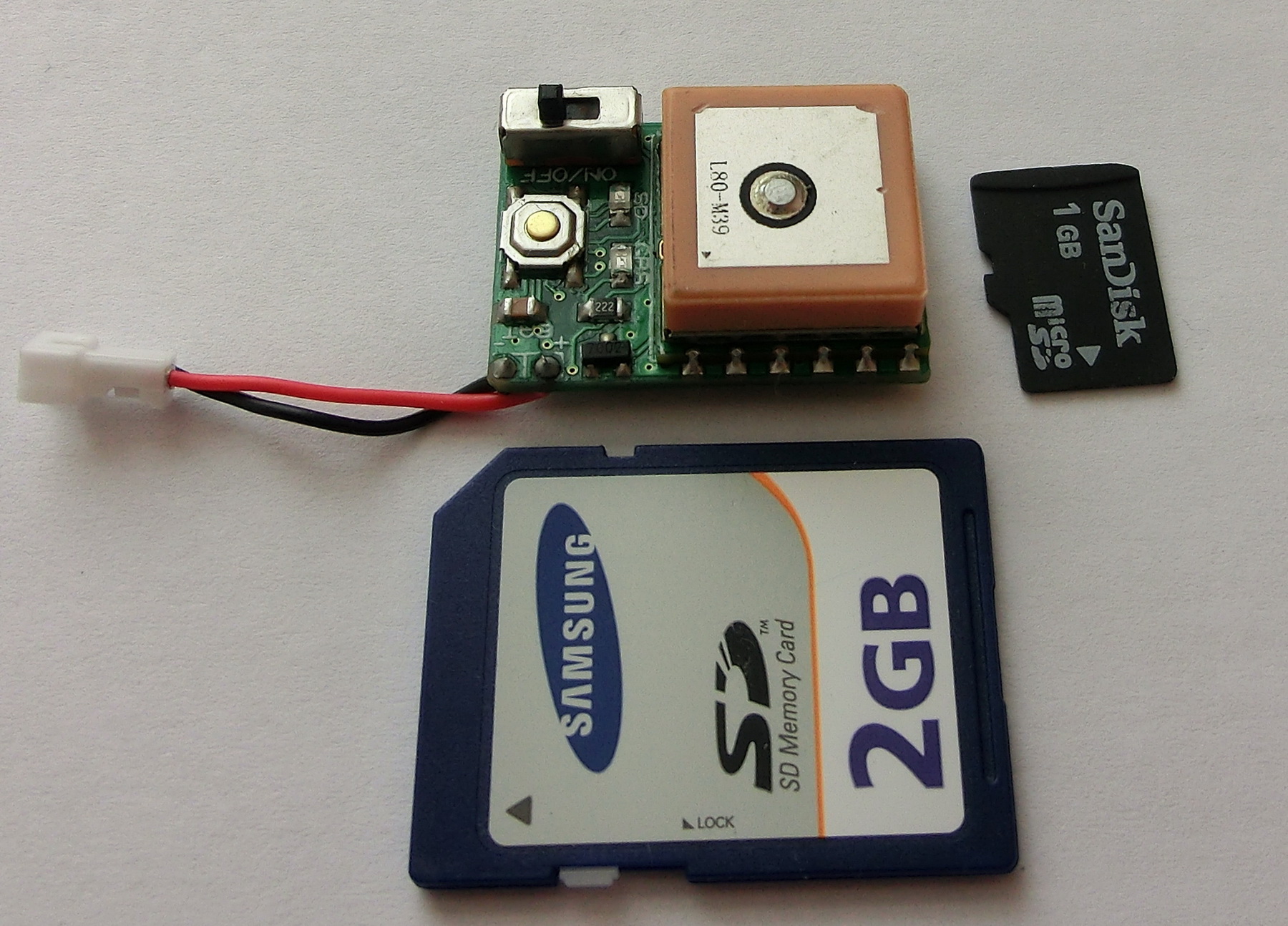
Update Note: As mentioned the SD card should be 2GB or less and formatted as FAT16. Due to addressing restrictions the SD card should contain only one partition, created as PRIMARY PARTITION with no unallocated space before the partition. Please note that some SD cards come with partitions, created as logical partitions and need to have their partitions recreated as mentioned previously.
As I mentioned in one of my comments in the older post MINI PIC GPS DATA LOGGER WITH MICRO-SD CARD I had plans to make a faster GPS data logger suitable for RC-Models and Model Rockets. Well the PCBs were ordered some time ago, but I finally found some free time to finish and describe the project.
DESCRIPTION
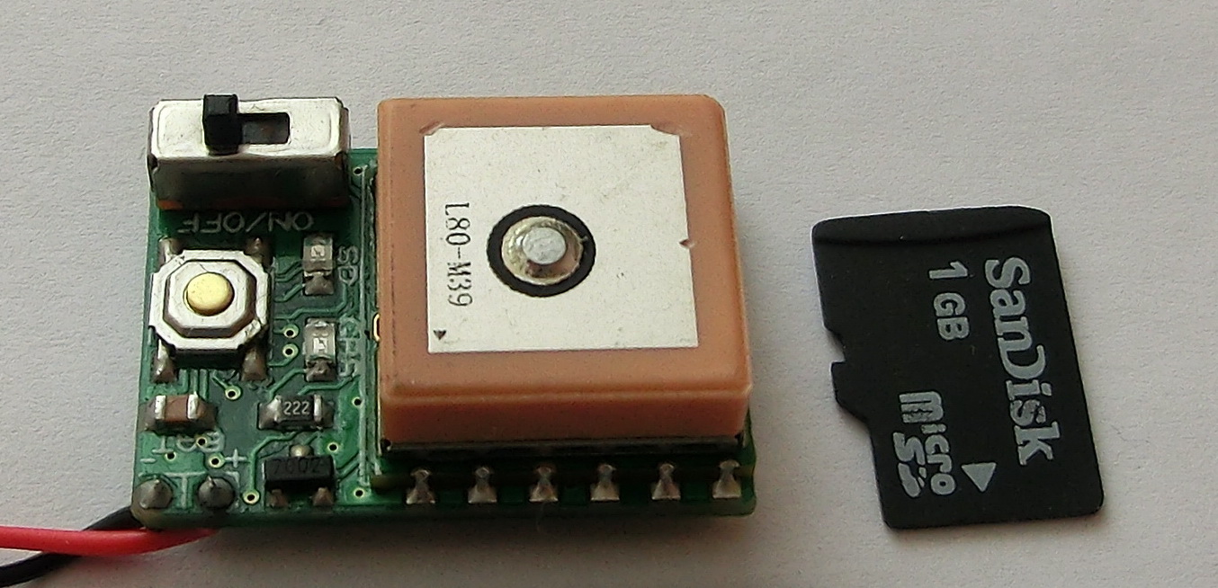
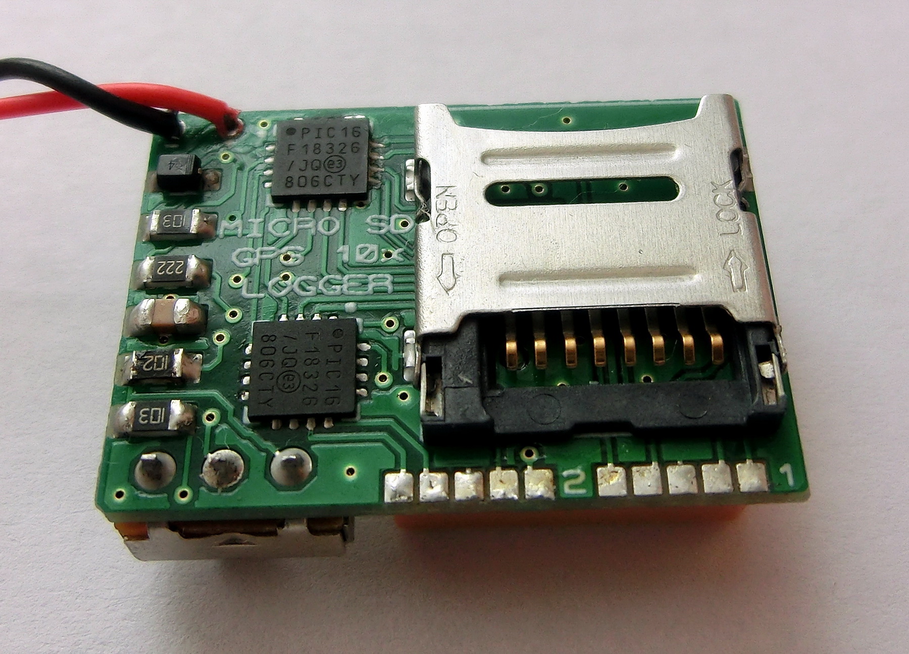
It has been already said that this GPS Data Logger, unlike the original version, is specifically designed for RC-models and model rockets. To make it as robust as possible and to accommodate the higher data transfer from the GPS module (10 Hz) and to the SD card, it was easier to change the large PIC18F25J11 MCU with the smaller PIC16F18325 and add a second MCU PIC16F18326 to control the SD data write. Thus one MCU is controlling the data transfer to and from the GPS module and passes the NMEA message to the second MCU, which on its turn write it to the SD card.
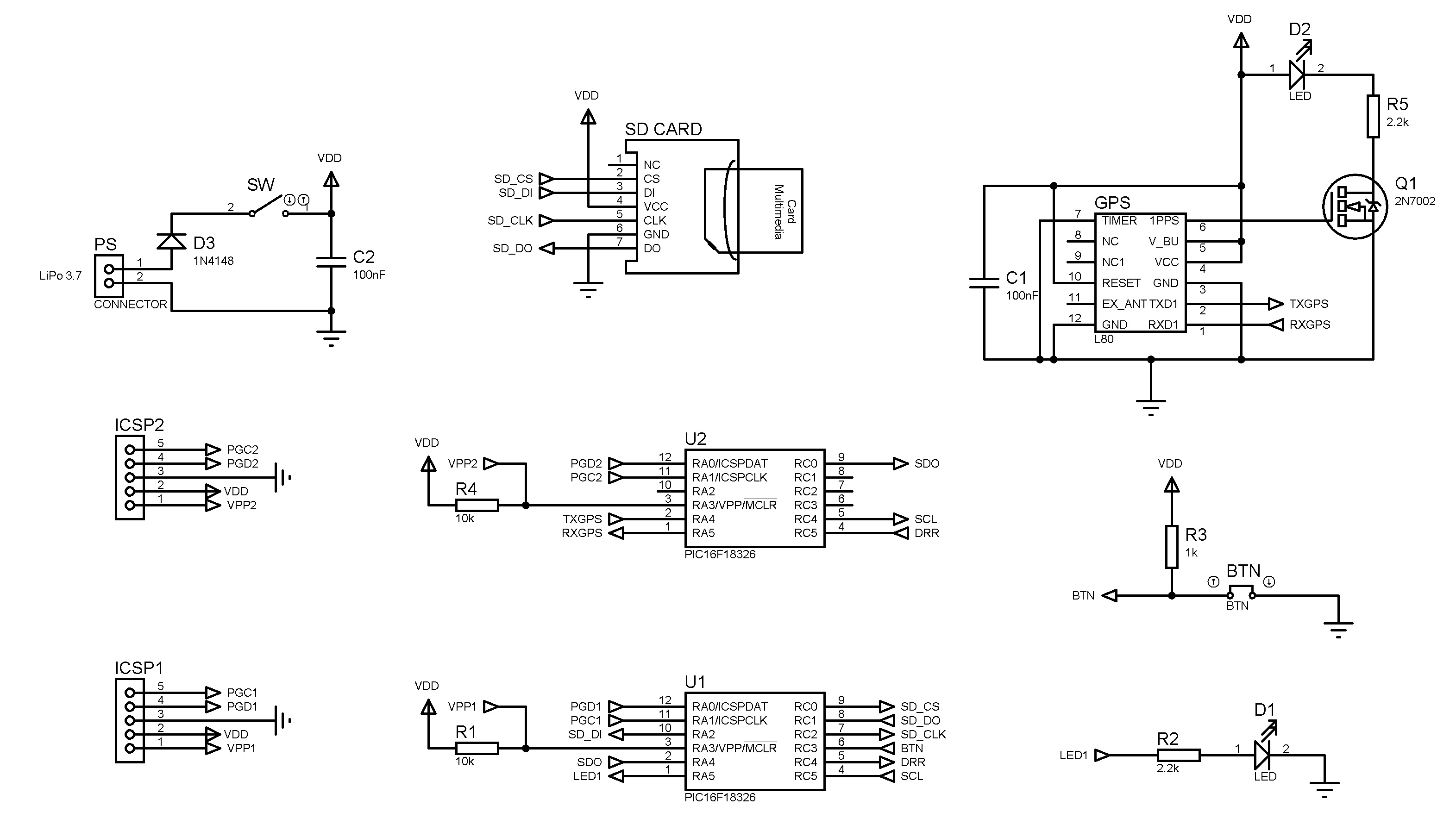
In fact the electrical design is quite simple and straightforward and all the work is done through the firmware of both MCUs.
SPECIFICATIONS
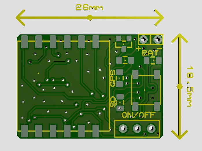
Despite the fact that there now two MCU’s this GPS data logger is actually a bit smaller than the original version 26×18.5 mm vs. the original 27×20 mm.
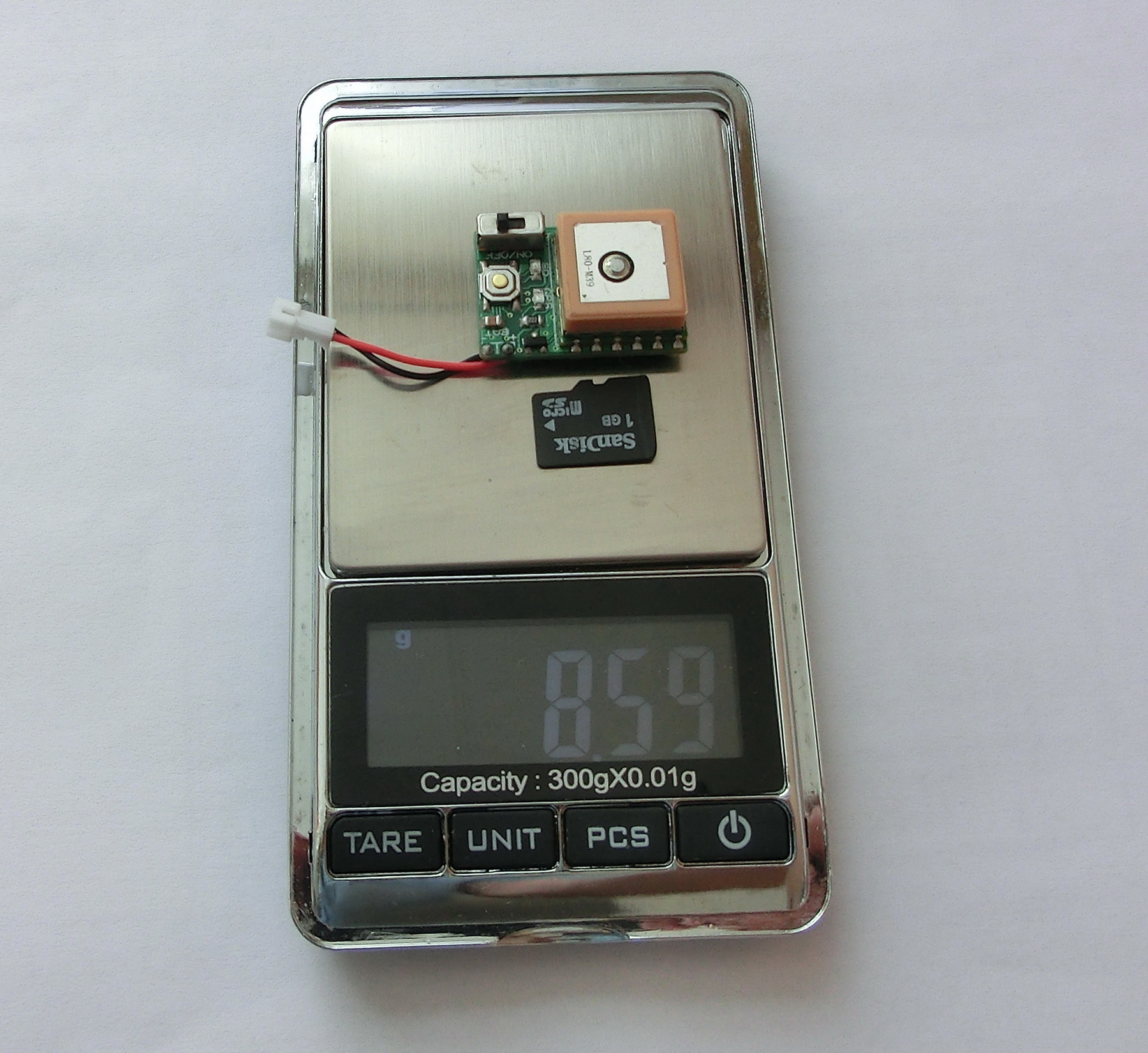
An important parameter is the weight – it is 8.6gr (including the micro SD card) where the biggest part, 6 gr, is due to the GPS module.
The power supply is from 3.3 to 4.2 volts maximum, i.e. the typical LiPo battery. Keep in mind that this GPS data logger is quite power hungry – 25mA from the GPS module, 3mA for each MCU and the typical 25mA for the SD card (which could be anywhere between 10mA and 100mA depending on the card) – this gives about 56mA typical consumption, which requires indeed a LiPo battery.
HOW TO USE IT
First you need a SD card with maximum size of 2Gb, formatted with FAT16. When you start the GPS data logger and:
- There is no SD card in the slot, the SD LED will remain off.
- If there is a card, but the MCU detected a problem with the SD card, then the SD LED will start blinking fast in regular intervals.
- Everything is OK with the card and no information is recorded, the SD LED will start blinking regularly every 1 second.
- Everything is OK with the card and information is being recorded, the SD LED will start blinking fast at irregular intervals.
To start the data record you have to press the small button, at which point every NMEA GPGGA message from the GPS module will start being recorded in the SD card.
To stop the data record, you have to press again the small button and wait until the SD LED starts blinking in long regular intervals, at which point it is save to remove the SD card or switch off the power.
SD DATA STRUCTURE
Because the GPS data logger is intended for use with RC-models and model rockets, the chances of power failure and hard landings are real, therefore care has been taken to ensure some data protection in case of emergencies.
The main problem with data files is that in case of sudden power failure (or lost pin contact) if a file is open for writing and/or data is being written, then the file will be corrupted and won’t be accessible through the ordinary PC interface.
To limit this possibility of file corruption, the MCU creates a new file to be written into every 15 seconds. So in case of emergency, unless there is a physical damage to the SD card, there is a possibility of file corruption only to the last file being written into, hence the maximum loss is limited to last 15 seconds or less.
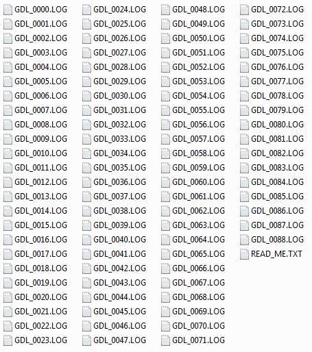
Every file has a sequential number and if you start a new record while the previous files are still on SD card, the record will be resumed from the last file in an uninterrupted sequence starting from 0000 – so if have files 0000, 0001, 0002, 0004, 0005, the GPS logger will resume as file 0003 and not 0006. If file 0000 is missing, it will resume from there and all other files will be ignored. So if you delete and keep files on the SD, keep that in mind.
DATA STRUCTURE AND DATA MANIPULATION
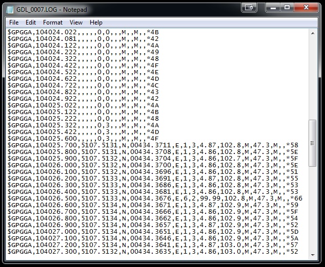
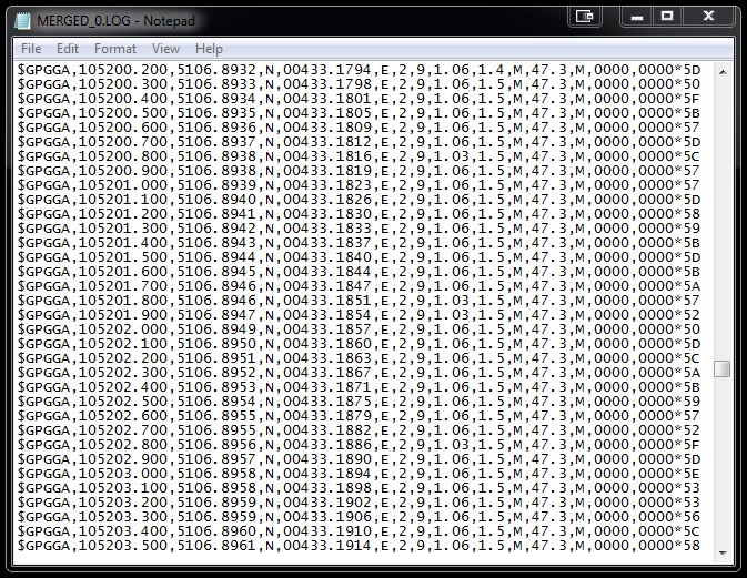
Each “GDL_XXXX.LOG” contains the raw GPGGA NMEA message, either with or without meaningful information, from the GPS module for 15 seconds in 100 milliseconds time increments.
To help with the data manipulation I wrote a small program which can combine multiple sequential files into various different file types which can be further used by other programs, while keeping the existing information and/or extracting and computing additional parameters.
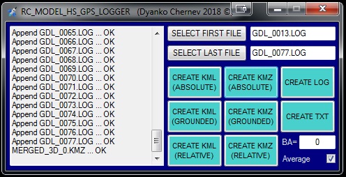
First you have to select the FIRST FILE and the LAST FILE in the sequence, which should be in the same folder. The sequence of the LAST FILE should be greater or equal to that of the FIRST FILE.
BA (Basic Altitude) – enter the basic Altitude(WGS84 ellipsoid) to be subtracted from each Altitude(WGS84 ellipsoid) point in order to calculate the relative altitude as referenced to the Basic Altitude. It is practical the basic ABSOLUTE ALTITUDE to be a point concurrent with the 3D map’s ground, so all points will be most correctly displayed.
Average – will apply a moving average with a window of 3 to coordinates and additional moving average of 2 to speed. This will result in smoother paths and more accurate calculations, although with a small time-lag in the data set.
For each newly created file an index number is given. Again, like with the SD card, the index continues from the last file in an uninterrupted sequence starting from 0.
“CREATE LOG BUTTON” – Ex. MERGED_0.LOG
Will simply merge all files in the sequence into one file without any data processing or formatting. The new file is called “MERGED_X.LOG”
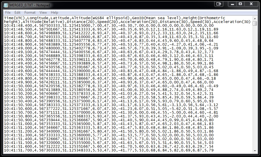
“CREATE TEXT BUTTON” – Ex. MERGED_0.TXT
For each line in the entire sequence, specific information is being extracted and/or computed and further written into a new file, called “MERGED_X.TXT”. The data for each point which this file contains is:
Time(UTC) – As per GPS, Coordinated Universal Time
Longitude – GPS data converted to decimal degrees
Latitude – GPS data converted to decimal degrees
Altitude(WGS84 ellipsoid) – As per GPS, altitude above ellipsoid
GeoID(Mean sea level) – As per GPS, GeoID or Mean Sea Level height
Height(Orthometric height) – Positional height above ground, computed as Altitude – GeoID
Altitude(Relative) – Altitude, relative to the Basic Altitude, computed as Altitude – Basic Altitude
Distance(2D) – Distance between two points, as projected on the ground, computed from Longitude and Latitude for each point
Speed(2D) – Instantaneous speed between two points, computed from Distance(2D) and 0.1 sec time frame
Acceleration(2D) – Instantaneous acceleration between two points, computed from Speed(2D) and 0.1 sec time frame
Distance(3D) – Distance between two points, as they appear in the space, computed from Longitude, Latitude and Altitude for each point
Speed(3D)- Instantaneous speed between two points, computed from Distance(3D) and 0.1 sec time frame
Acceleration(3D) – Instantaneous acceleration between two points, computed from Speed(3D) and 0.1 sec time frame
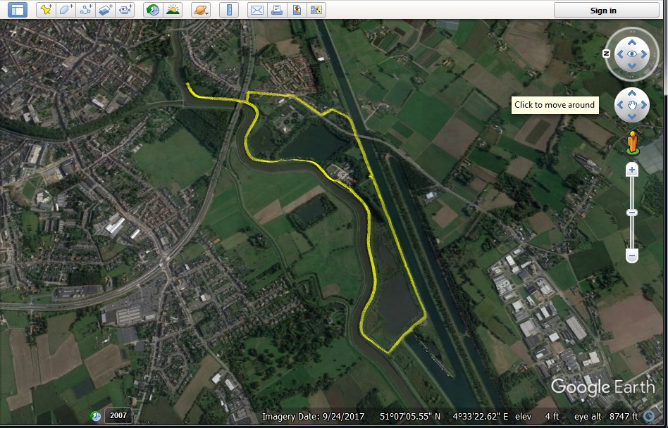
“CREATE KML (ABSOLUTE) BUTTON” – Ex. MERGED_3D_0.KML
Creates a KML file, with a name “MERGED_3D_X.KML” which can be opened for example by Google Earth.
This KML file describes the data set as a 3D track, using the Altitude(WGS84 ellipsoid) referenced to the mean sea level.
“CREATE KMZ (ABSOLUTE) BUTTON” – Ex. MERGED_3D_0.KMZ
Creates a KMZ file, with a name “MERGED_3D_X.KMZ” which can be opened for example by Google Earth.
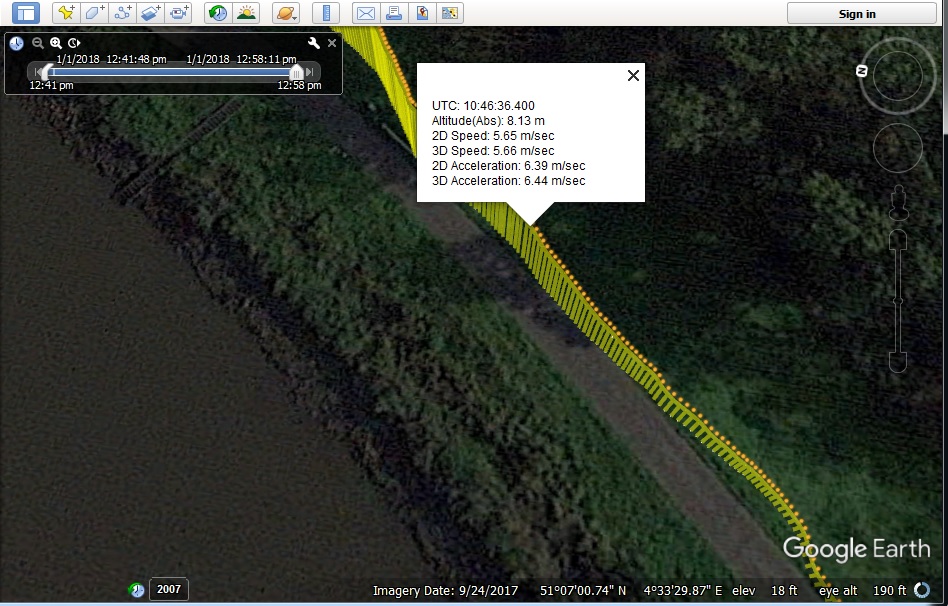
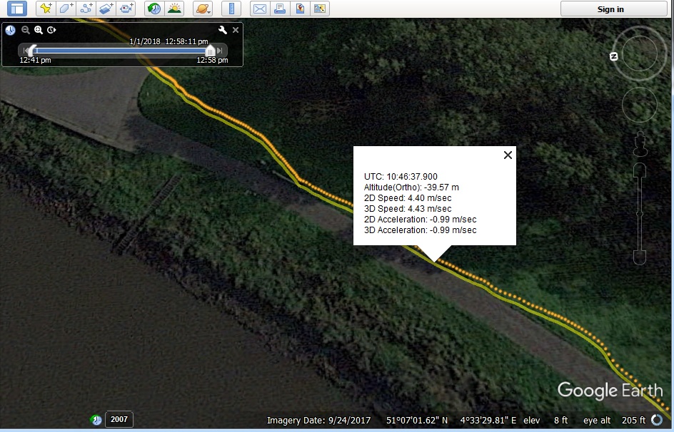
This KML file describes the data set as a 3D track and 3D Points set, using the Altitude(WGS84 ellipsoid) referenced to the mean sea level. Each point offers additional information as balloon tip and contains a time stamp which allows the track to be animated.
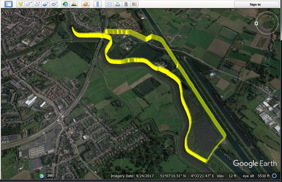
“CREATE KML (GROUNDED) BUTTON” – Ex. MERGED_2D_0.KML
Creates a KML file, with a name “MERGED_2D_X.KML” which can be opened for example by Google Earth.
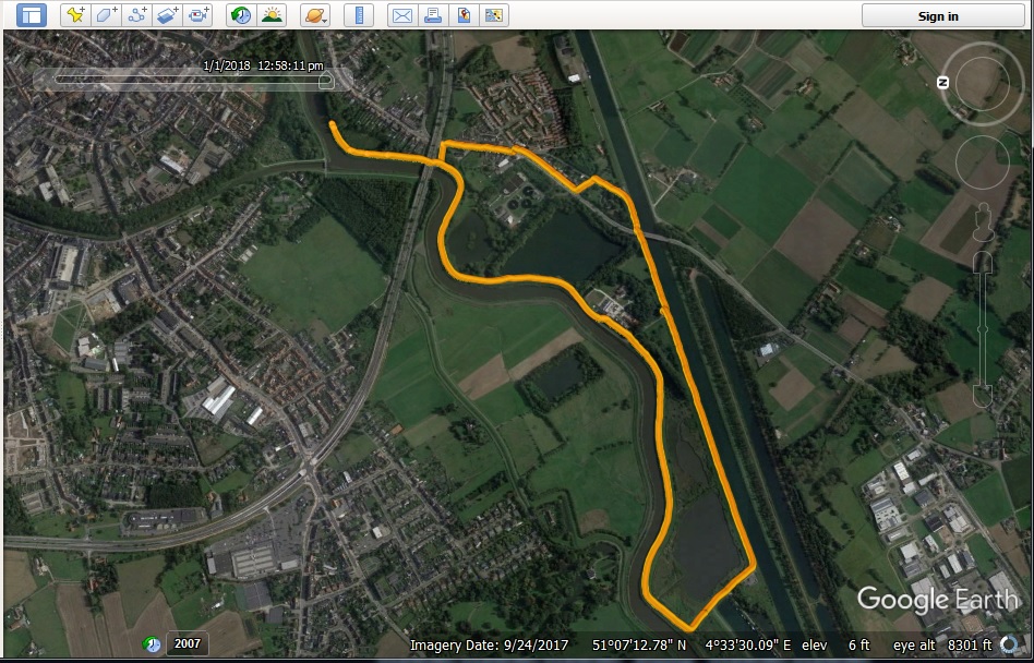
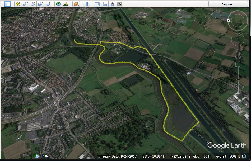
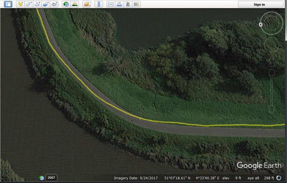
This KML file describes the data set as a 2D track projection over ground.
“CREATE KMZ (GROUNDED) BUTTON” – Ex. MERGED_2D_0.KMZ
Creates a KMZ file, with a name “MERGED_2D_X.KMZ” which can be opened for example by Google Earth.
This KML file describes the data set as a 2D track projection over ground and 2D Points set. Each point offers additional information as balloon tip and contains a time stamp which allows the track to be animated.
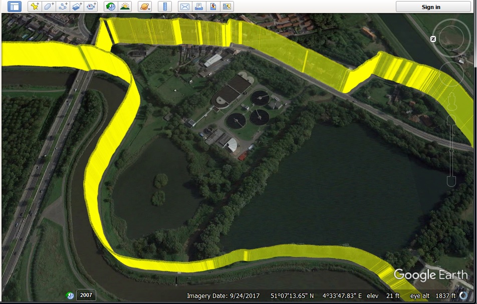
“CREATE KML (RELATIVE) BUTTON” – Ex. MERGED_3DR_0.KML
Creates a KML file, with a name “MERGED_3DR_X.KML” which can be opened for example by Google Earth.
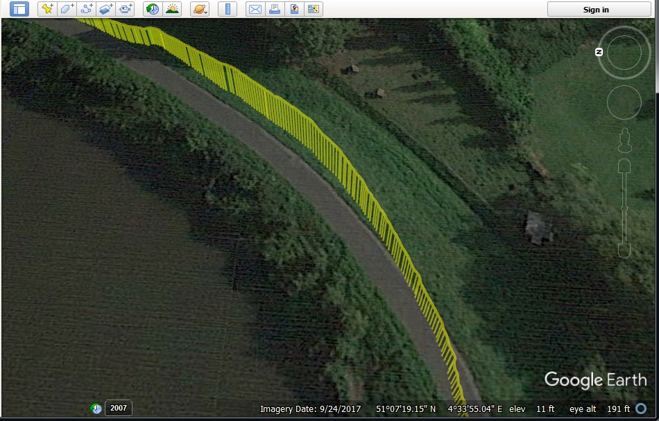
This KML file describes the data set as a 3D track, using the Relative altitude (referenced to the value entered in the Basic Altitude box) as height over the map’s ground level .
This is the best way to display 3D paths since GPS absolute altitude accuracy is quite poor (normally +-30m) but its relative (point to point) short term accuracy is much better.
*For better understanding how this option works, I exaggerated and added 50 meters (remember the value is being subtracted, thus negative 50m actually adds 50m) to the relative altitude.
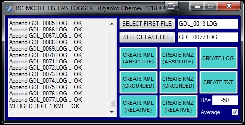
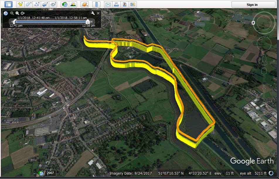
“CREATE KMZ (RELATIVE) BUTTON” – Ex. MERGED_3DR_0.KMZ
Creates a KMZ file, with a name “MERGED_3DR_X.KMZ” which can be opened for example by Google Earth.
This KML file describes the data set as a 3D track and 3D Points set, using the Relative altitude (referenced to the value entered in the Basic Altitude box) as height over the map’s ground level. Each point offers additional information as balloon tip and contains a time stamp which allows the track to be animated.
This is the best way to display 3D paths since GPS absolute altitude accuracy is quite poor (normally +-30m) but its relative (point to point) short term accuracy is much better.
*For better understanding how this option works, I exaggerated and added 50 meters (remember the value is being subtracted, thus negative 50m actually adds 50m) to the relative altitude.
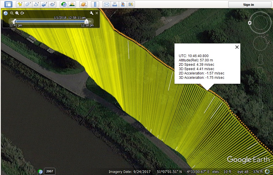
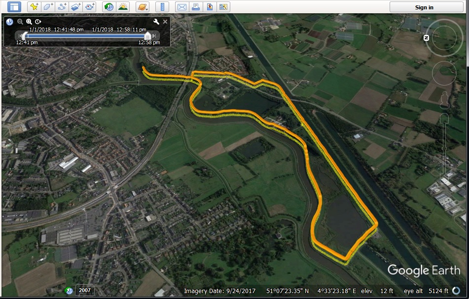
THE KMZ – short video showing the advantages of the KMZ files i.e. timed animation capability and additional data display. First video is with a 3D KMZ and the second video is with a 2D KMZ file, when the altitude is not needed, also you can see the difference between averaged and not averaged data.
I did not have a chance, so far, to test the GPS Data Logger with an RC-Model or Model Rocket and the displayed data set and tracks are record of me riding my bike around.
Also keep in mind that using large data sets with too many points for animation in Google Earth will put a considerable strain on your machine and might be too slow for smooth display.
One last note, the GPS module should be L80 and not L80R because, although they have the same pin-out and dimensions, the latter is not capable of 10Hz output.
SOFTWARE
FIRMWARE
PCB MANUFACTURING FILES
EXAMPLE LOGS DATA SET
Hi,
Regarding Flashing the PIC chips.
What hardware do you use?
Do you flash with the chip insitu via the pads.
Regards
Peter
Hi Peter,
I am using PICkit 3 In-Circuit Debugger and the programming is via the pads (ICSP1 and ICSP2) connected to the ICSP ports of the corresponding MCU.
Hi Pinko,
Thanks for the info 🙂
Is there a way to export the data compatible with dashware video overlay GPS software?
Hi, I’ve never used Dashware before but from what I read you can create custom profiles for GPS data import – maybe this is the way to go.
Fantastic, can i buy this 10hz gps logger from you?
Hi,
Is there any PCB already fitted with all the components to buy?
Or need to print the PCB and gather all the components and soldering by myself?
Thank you
Hello,
I don’t have any spare assembled units at the moment.
Regards
All right, thank you.
When you get one can you please contact me?
Thank you
Hi! Very nice project. I’m designing a flight computer for a high power model rocket. And there is a forum post on the rocketryForum and they say “Chipset of this module ‘L80’ is not suitable for rockets unless you change the dynamic modes”.
Did you change these modes?
I haven’t seen a backup battery for the GPS. To save these configurations there must be this battery. If you changing configurations, How did you do that?
Thank you!!!
Hello,
as far as I know you can’t change the mode in L80, probably they meant L80-R which has “Baloon”, “Dyanmic” and “Normal” modes. L80-R has some additional futures and one drawback – 5Hz update rate vs 10Hz for L-80.
You don’t need a battery to save any configuration changes – some can be written in the internal memory others need to be updated at each power reset. In any case any changes in the settings can be simply sent at each power-up cycle.
Any (or 99.9%) commercial modules come with the COCOM limitations. In some modules the conditions are “AND” – that’s to say they will stop outputting messages if all limits are met – 18km altitude AND +515m/sec AND +4g. For this module the conditions are “OR” – as soon as one of those limits is met, it stops outputting NMEA messages.
This module is still quite suitable for low and mid power rockets. In my experience, as I mentioned, as soon as one of the COCOM limits is met it stops giving NMEA messages but right after it falls again within the limits, the module continues outputting the NMEA messages.
Just think for how long your rocket will stay outside any of the COCOM limits – probably 4-5 seconds, in any case you can not rely on the GPS module for accurate data during and after the burn-out because of the inaccurate altitude positioning and in this stage of the flight an inertial measurement system is much more accurate.
Regards
Thank you. This information is perfect. I will use the GPS only for the recovery after landing. So this means even if I use this module with default configurations, I can read the NMEA messages. That’s perfect.
I Build this for speed checking and examining my RC models flight path and its excellent, light accurate and works reliable. Many thanks to make this available to us!!
But I have one question in GPSPrune speed is displayed correctly thought the whole recorded data from the KMZ data but not in Google Earth speed graph where only some spikes are shown and not the real measured speed data, but clicking each point gives the correct value in m/s. What could be the problem for this? I tried every possible export in your software and all possible settings in Google Earth but no luck.
Hello Andrej,
I am guessing that the path is “hiding” in the ground and needs to be shifted upwards. Could you send me a sample KMZ file and a screenshot from Google Earth showing this problem – you can use the contact form for that.
Regards