
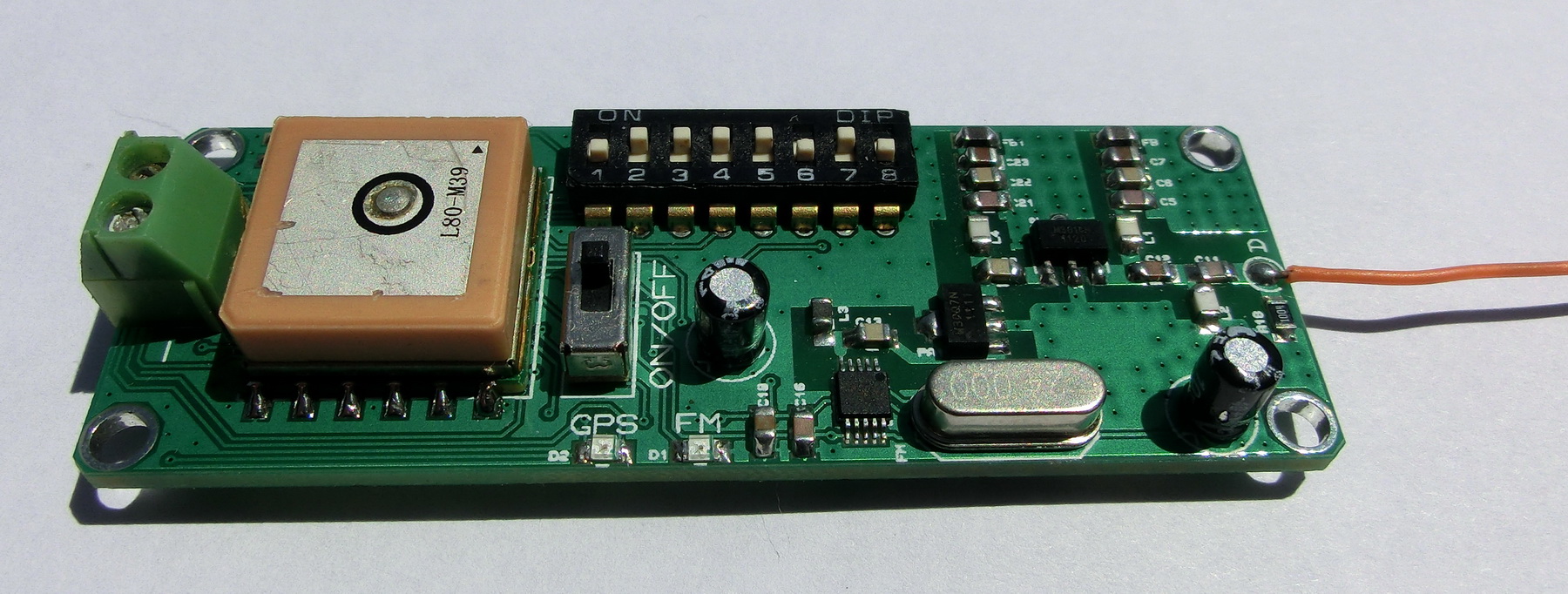
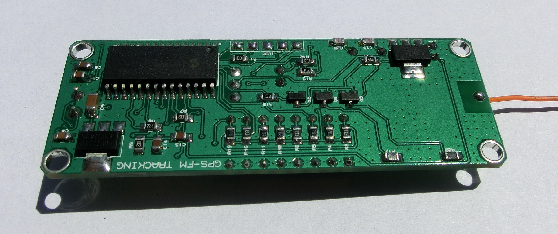
Today I made some modifications to this is a new project for a GPS to FM radio tracking device for rockets i.e. the V2. The initial design lacked the antenna impedance matching circuit which caused problems with the end amplifier. Also I increased the possible choices of frequencies, see the table further down. Now instead of soldering and de-soldering tiny resistors, the frequency and the transmitting modes are selected via a DIP switch.
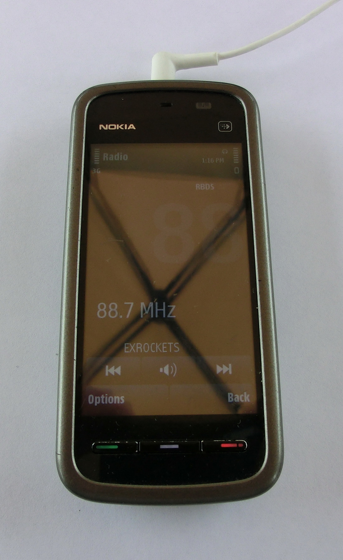
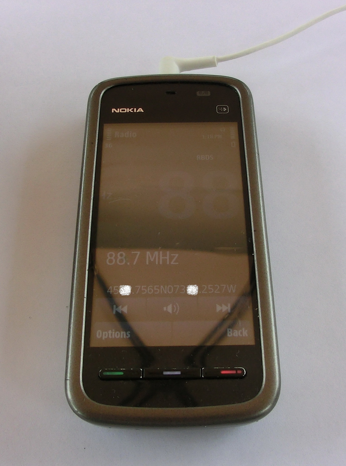
Another change is the addition of FM RDS functionality – the GPS coordinates are simultaneously transmitted via the RDS channel. However this function is not really reliable and as any RDS system, it needs a strong signal for error-free RDS text.
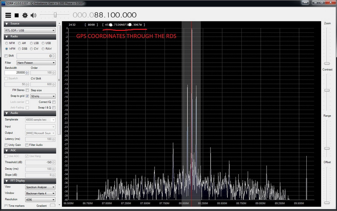
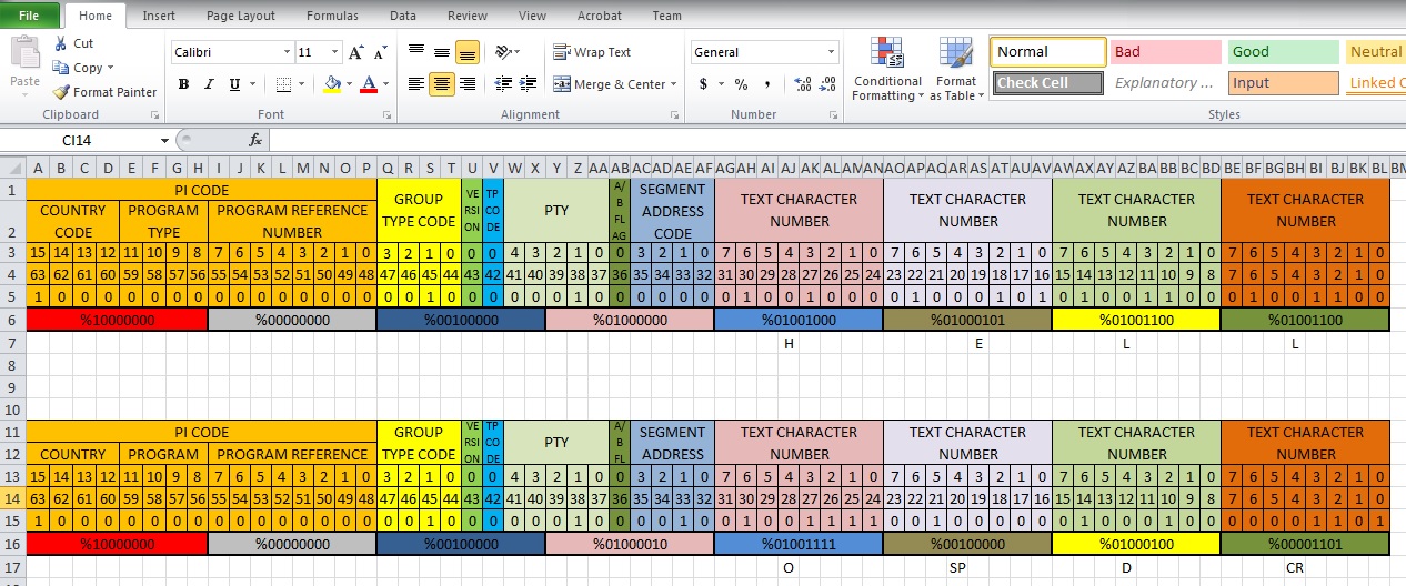
As an aid for calculating the RDS 8 bytes I made an Excel spreadsheet that can give the 8 bytes in a binary form, which makes it easier to read and calculate the RDS words. More information about the RDS standard you can find in the pdf file at the bottom of the page.
What is interesting in this project is that the device will actually speak the coordinates over the FM radio in the 88-107 MHz band so you won’t need a special receiver to track the rocket.
for example if the GPS coordinates are: “Latitude: 42 59.6281N, Longitude: 024 51.5161E, Altitude: 0850.7m”
what you actually will hear on your ordinary FM radio receiver (depending on what data mode you selected – see down) will be: “FOUR, TWO, FIVE, NINE, POINT, SIX, TWO, EIGHT, ONE, NORTH, ZERO, TWO, FOUR, FIVE, ONE, POINT, FIVE, ONE, SIX, ONE, EAST, EIGHT, FIVE, ZERO, POINT, SEVEN”
This device has four functional modules as shown on the general diagram:
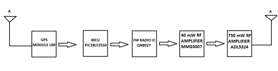
1. GPS module – decodes the satellite information and sends the NMEA messages to the microcontroller
2. Microcontroller – Decodes the NMEA message from the GPS and generates the audio signal, that is being sent to the FM modulator
3. FM modulator – generates the FM signal and carrier frequency
4. RF amplifier – amplifies the FM signal that is being transmitted
And the actual schematic looks like this:
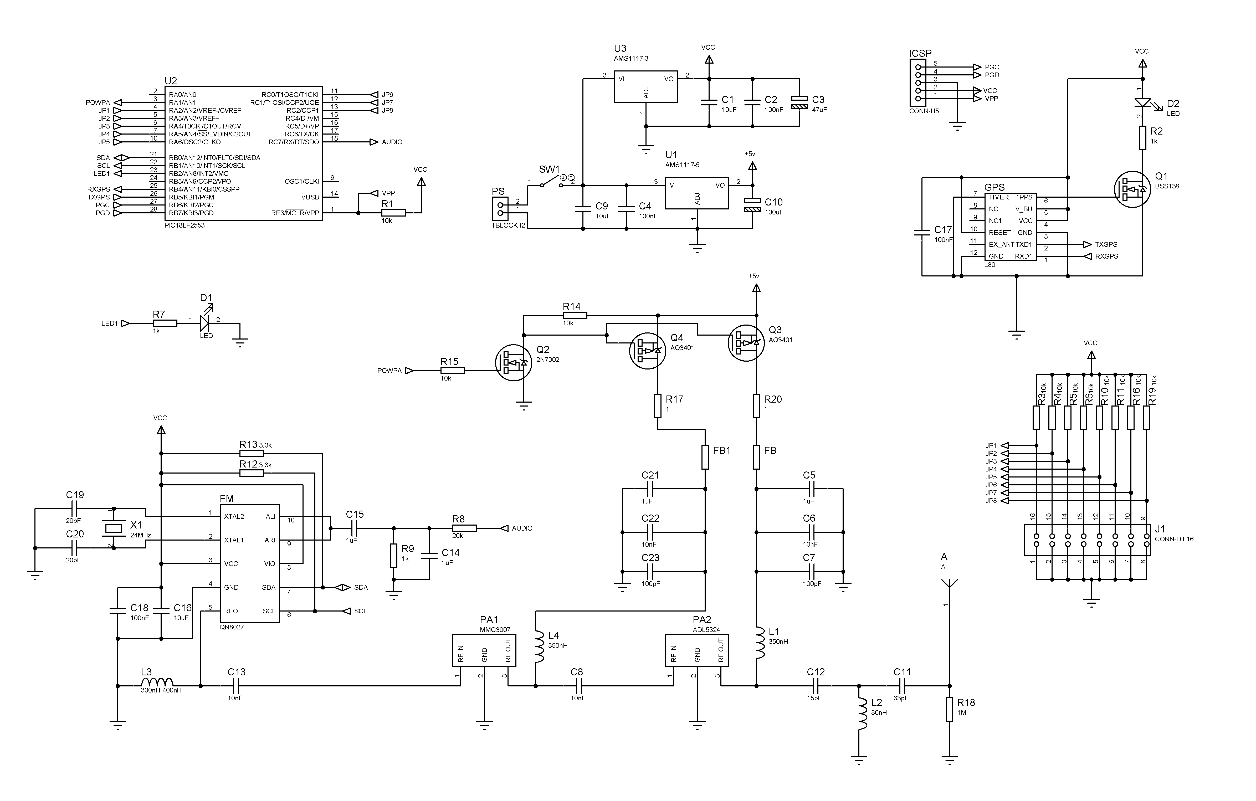
More information about each part of the design:
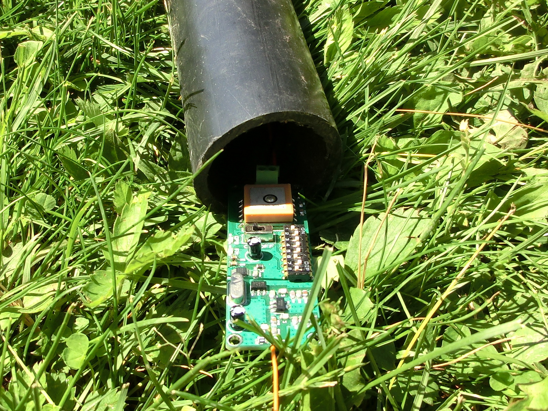
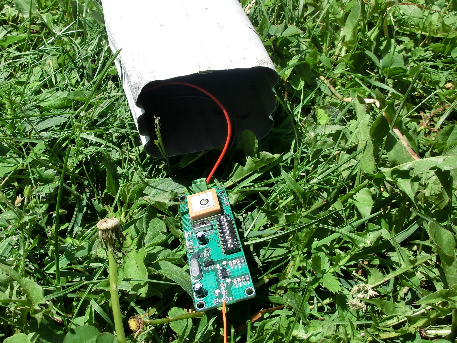
1. The GPS module (Quectel L80) is a very inexpensive GPS module from China while having excellent reception. After a cold start, the time to first fix is about 60-90 seconds. For the moment I have tested this module only on the open ground or in a plastic box while the antenna was facing down. So far I haven’t seen any difference in the time to first fix or degradation in the accuracy. However I plan to conduct more tests.
2. The MCU is Microchip PIC18LF2550. This microcontroller decodes the NMEA messages from the GPS module and generates the audio signal (speech) that will be transmitted from the FM modulator according the jumper settings. Instead of the ordinary PC jumpers this time I am using small 0-Ohm resistors to save space. These jumpers can set the Data Transmission Mode, FM Frequency and Message Frequency (how often to transmit the coordinates over the radio):
a) DM (Data Mode) switch (SW8) – set two transmission modes:
– Full (DM jumper off) – if selected then the MCU will generate audio for the full set of coordinates and altitude i.e. degrees and minutes + heading + altitude. For example if (Latitude: 42 59.6281N, Longitude: 024 51.5161E, Altitude: 0850.7m), you will hear (FOUR, TWO, FIVE, NINE, POINT, SIX, TWO, EIGHT, ONE, NORTH, ZERO, TWO, FOUR, FIVE, ONE, POINT, FIVE, ONE, SIX, ONE, EAST, EIGHT, FIVE, ZERO, POINT, SEVEN)
– Short (DM jumper on) – if selected the MCU will generate audio only for the minutes and heading from the set of coordinates. For example if (Latitude: 42 59.6281N, Longitude: 024 51.5161E, Altitude: 0850.7m), you will hear (FIVE, NINE, POINT, SIX, TWO, EIGHT, ONE, NORTH, FIVE, ONE, POINT, FIVE, ONE, SIX, ONE, EAST)
b) TR1 (SW6) and TR2 (SW7) selects the transmission period as follows:
TR1=ON and TR2=ON /every 60 seconds
TR1=ON and TR2=OFF /every 45 seconds
TR1=OFF and TR2=ON /every 30 seconds
TR1=OFF and TR2=OFF /every 15 seconds
c) SW1, SW2, SW3, SW4 and SW5 (FM frequency) set the FM transmission frequency as follows:
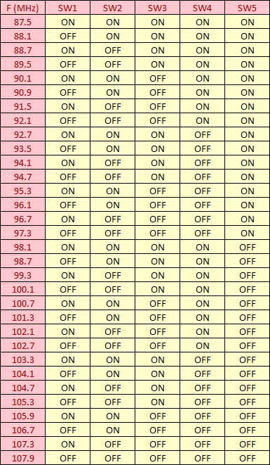
I have selected in my MCU firmware those 32 frequencies in equal intervals from 88 to 107 MHz but in practice I could have set any frequency from 76 to 116 MHz.
3. The FM modulator (QN8027) is very inexpensive, less than 50 cents, complete FM radio transmitter on a single chip that requires only two external components – a 12/24 MHz crystal and any low quality single value chip inductor with inductance anywhere between 150nH and 400nH.
After some testing I was amazed from the quality of those FM modulators. The frequency s extremely stable and even touching the IC and the RF paths didn’t cause a change in the frequency more than 0.005MHz. In addition this chip offers the possibility to send RDS information as well and it can be used to send the coordinates too.
4. RF amplifier – this is a two stage amplifier consisting of one MMG3007NT1 and one ADL5324 Class A amplifiers. The output power is about 600-750mW or near 28dBm. The ADL5324 is not rated for such power output but because the transmission bursts are only between 2.5 and 5 second it is holding well.
PIC18F2550 Audio playback:
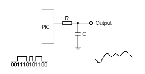
Audio playback is realized by a PWM technique where the MCU output pin is being held HIGH or LOW for a predetermined period of time, the signal is being shaped by a low pass RC filter and then fed through a DC blocking capacitor to the FM modulator.
So how to make our PIC MCU able to speak the coordinates, the actual procedure look like:
1. Generate your *.wav files that will be used for creating the speech dictionary (in my case the digits from 0 to 9, North, South, East, West, Point and No Fix)
2. Convert the *wav files into 1 bit audio stream using the BTc Sound Compression Algorithm from Roman Black, more information and the conversion software can be found here. Then every word in the dictionary can be written to the memory as a byte series with a start and an end address. Looks like that, but much larger string (…$5a,$d5,$ab,$55,$29,$4a,$4a,$48, $84,$21,$65,$ef,$df,$b6,$aa,$69,$52,$a5,$29,$4a,$59,$ad,$b6,$ed,$b5,$55,$49,$21,$0, $40,$63,$d7,$ef,$fc,$d9,$65,$55,$2a,$55,$55,$56,$ad,$55,$ac,$a9, …)
3. Once the digits and headings from the GPS NMEA message have been decoded it is time to create the sentence. What it means is to determine what words and the sequence in which the words from the dictionary will be played. The actual programming can be different depending on what language you are using but the general idea is as follows:
From WORD_START_ADDRESS to WORD_END_ADDRESS read Byte0. Then from Bit.7 to Bit.0 in Byte.0 set the output pin equal to Bit.7, wait N microseconds, then set the output pin equal to Bit.6, wait N microseconds …. set the output pin equal to Bit.0, wait N microseconds. Then read Byte1 and from Bit.7 to Bit.0 in Byte.1 set the output pin equal to Bit.7, wait N microseconds, then set the output pin equal to Bit.6, wait N microseconds …. set the output pin equal to Bit.0, wait N microseconds… and so on until you reach the WORD_END_ADDRESS.
*N microseconds – this waiting period depends on your *.wav file sampling rate. If it is 16kHz then the waiting period N=1/F or N=1/16000 = 62.5 usec.
Because the PIC18LF2550 MCU that I am using has only 32kB programing memory I was able to fit only one language dictionary. But in case I decide to implement more or larger dictionaries it could be done by adding and external I2C or SPI memory that can be pre-programmed with the dictionaries.
This tracking device has small dimensions only 25×70 mm. While transmitting, the power consumption is significant – about 130 -150mA, where in idle it is draining about 15mA. Although the power need, while transmitting is quite high, the RF amplifiers are on only for 2.5 – 5sec every transmission period or every 60/45/30/15 seconds.
I made a test on the field placing the transmitter on the ground and started driving away from the tracking device while listening on my car radio. The reception range was between 1.5 and 2 km, depending on which direction I was going away. I think with a good quality FM radio receiver and good antenna this reception range can be increased.
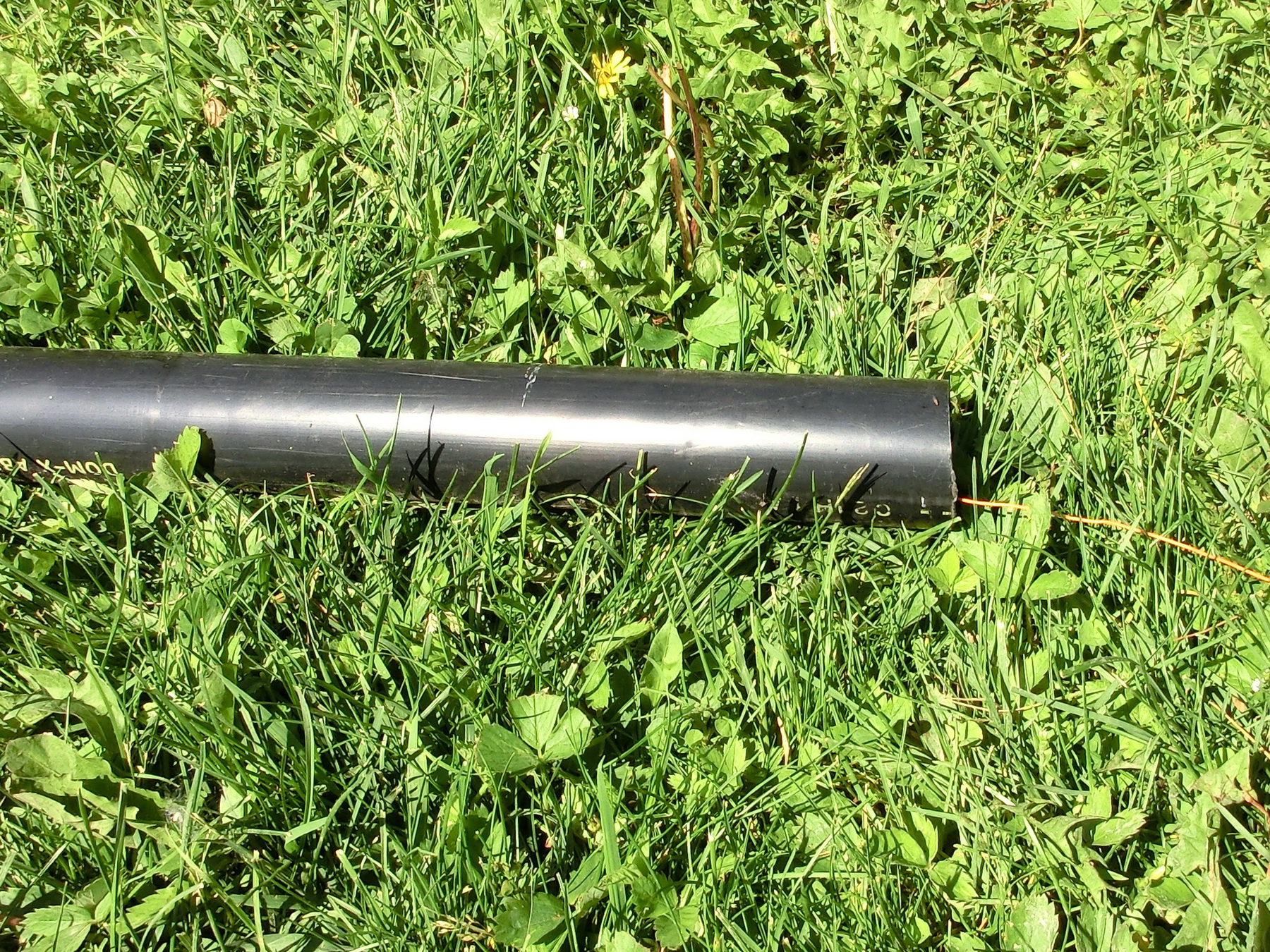
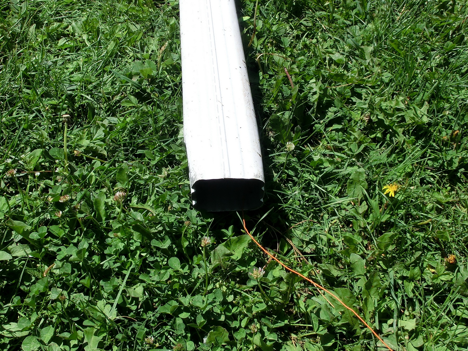
I run another set of tests to determine the GPS signal reception while the device is covered by different materials. The results are that the reception is good even in a thick ABS tube while the GPS antenna is pointing the ground, however a thin metal is sufficient to hinder the reception. So the conclusion is that the tracking device can be used in any non-metallic tubing, regardless its actual place in the rocket.
One last note, because this device exceeds the permitted power ratings in the FM 88-107MHz band it is not advisable to be used close to inhabited areas because it could interfere with some of the local stations if the same frequency is selected, besides you will be effectively transmitting your own GPS coordinates to everyone who is listening his radio on the same frequency. But anyway who will be launching rockets that need GPS tracking so close to inhabited places.
PCB_DESIGN_CADCAM
ENGLISH_VOICE_FIRMWARE
RUSSIAN_ VOICE_FIRMWARE
RDS_CALCULATOR.xlsx
RDS_STANDARD.pdf
It’s really amazing!! :)))