In order to synthesize chlorates and perchlorates in the home lab it is always good to have a way to regulate the current flowing through the electrolyte. Because the load is purely resistive the simplest solution is a small PWM (Pulse Width Modulation) regulator. So I decided to make my own.
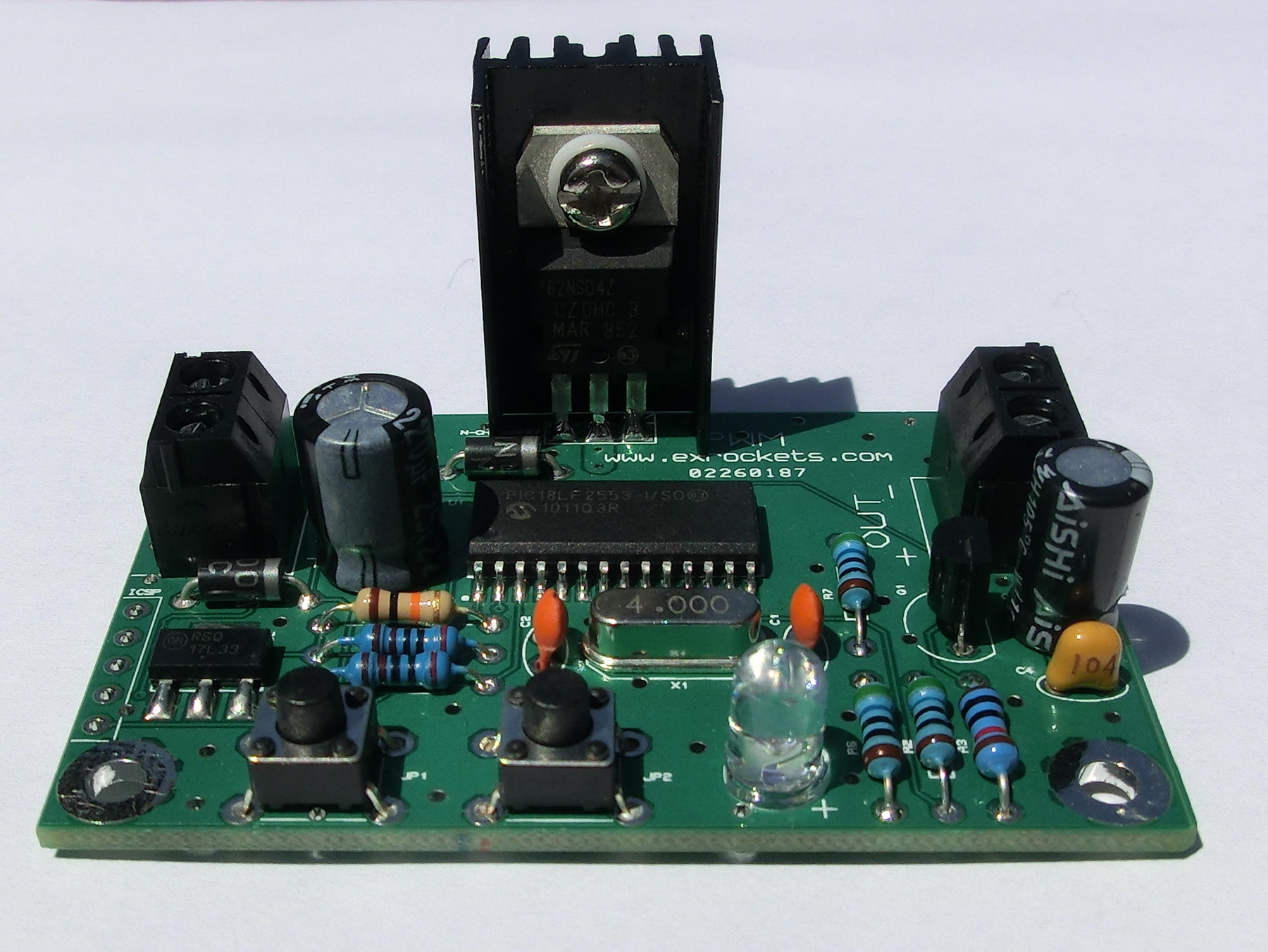
The schematic is very simple. It could be divided in two parts:
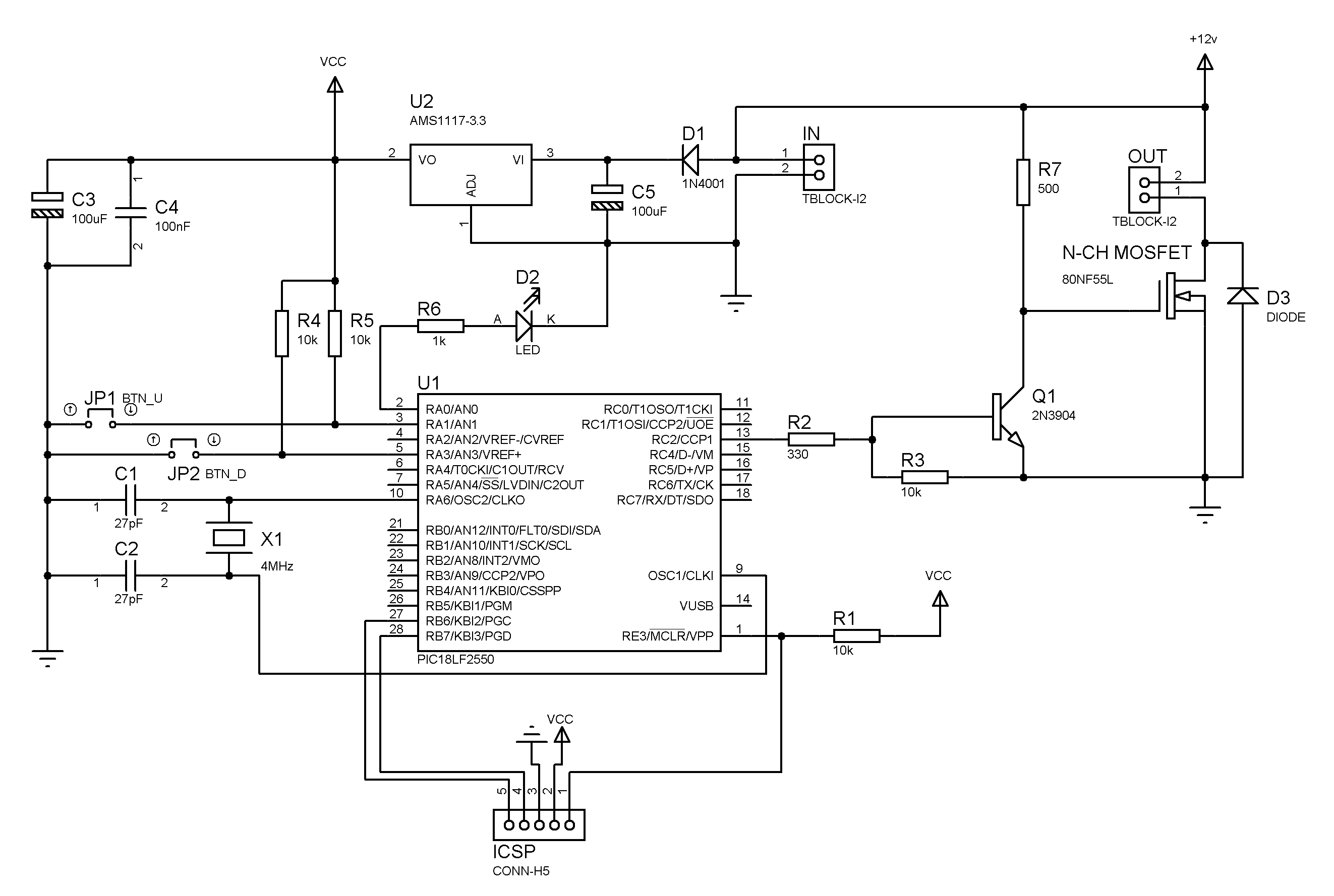
- PWM generator
- The MCU generates the pulses, which greatly simplifies the circuit.
- There are two buttons (UP and DOWN) respectively to increase and decrease the power.
- The LED is very crude indication of the pulse width – the faster it blinks the greater the duty cycle. If the LED is solid on then the duty cycle is 100% and if it is off then the duty cycle is 0%
- MCU power supply – this is a 3.3v LDO regulator – so depending on the MOSFET you can use power supply ranging from 3.7v to 25v.
- The switching frequency is 32 kHz and the pulse width is divided in 256 steps, including full ON and full OFF.
- Power MOSFET
- The driver for the MOSFET transistor is the common 2N3904.
- The power MOSFET transistor could be any suitable N-channel MOSFET.
- The power traces on this PCB are calculated for about 5-6 amps – if higher currents are needed then a simple bypass with a suitable wire will do.
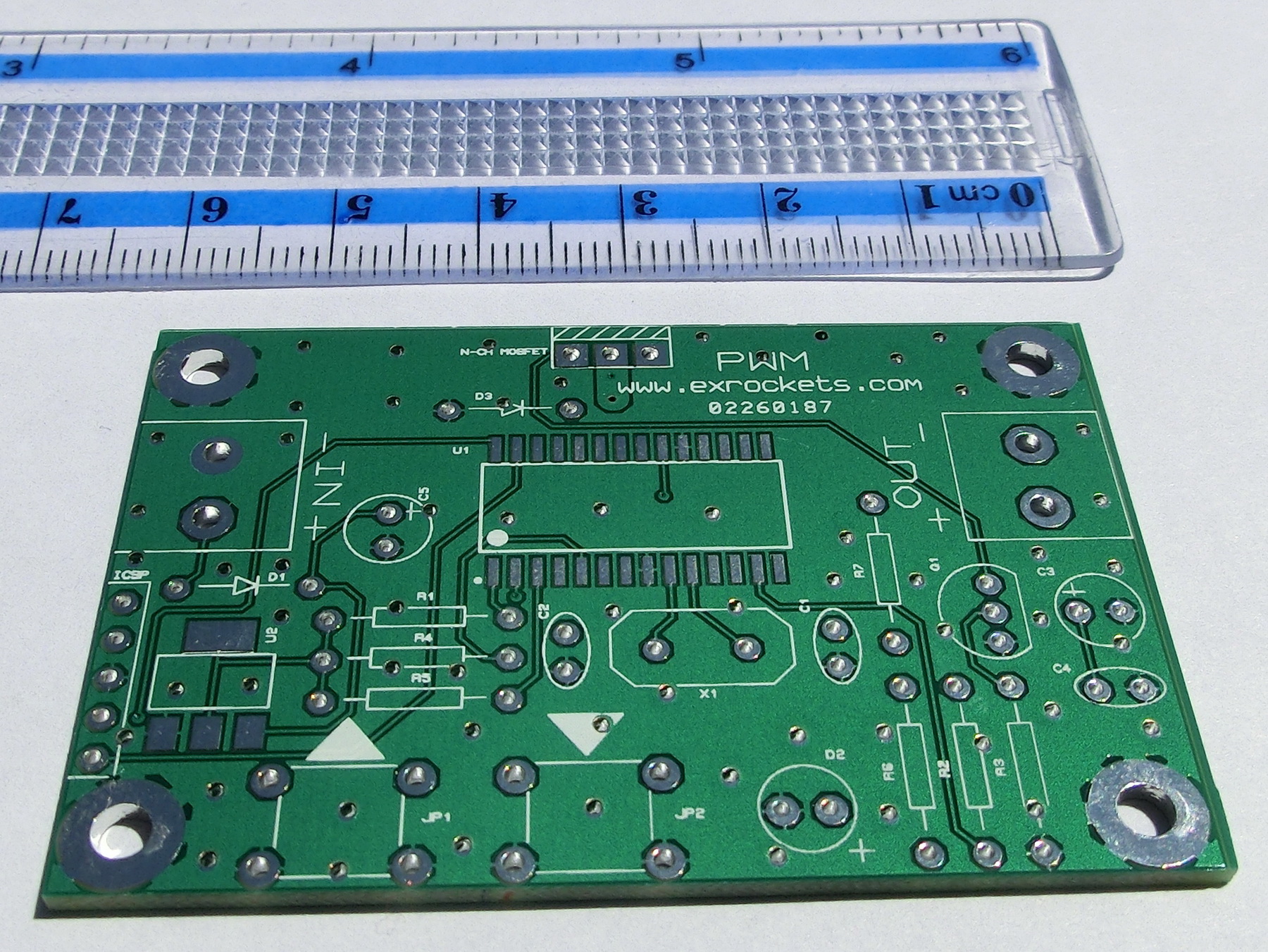
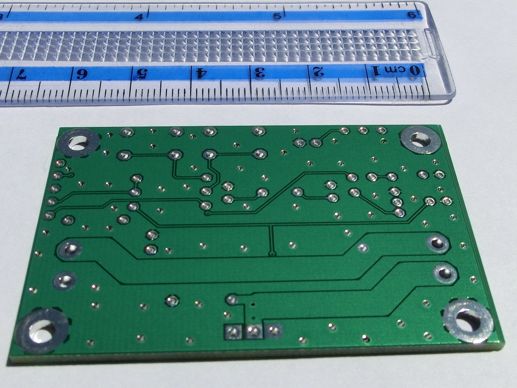
Nowadays the hobby PCB suppliers offer very affordable prices and I ordered few of the following PCBs that I prepared.
Finally a short video with a car bulb for demonstration.
PCB MANUFACTURING FILES (GERBER FORMAT)
MCU FIRMWARE (HEX FORMAT)
Leave a Reply