 Although the UV Apogee Detector 1 is completely functional after number of tests done in Bulgaria by -VMK- and vega and in Argentina by a_centaurus some things worth improving came to the light:
1. vega mentioned that the indicating LEDs (red and green) are not bright enough in a sunny day and instinctively one might try covering the device with a hand to make shadow so the LEDs can be seen. This is dangerous for two reasons – first you lean towards the rocket and second you risk activating the detector if you cover the upper UV led by error. What might happen in this case is that the parachute fires when you are near the rocket.
Thus I found nice ultra-bright red LEDs with clear lens on eBay that replace the green-red LEDs. The lens is transparent when the LED is off and red when it is on. The difference between on and off is visible even in the brightest day here.
2. -VMK- suggested to move the power supply LED before the blocking diode D3 so it won’t draw current from C1 when the igniter fires. Also he proposed to change the igniter detecting components i.e. the OP AMP with a MOSFET transistor in order to simplify the design. After reading several datasheets my choice for the MOSFET was the small 2N7002 which is also extremely cheap.
 3. When a_centaurus tested the apogee detector he mentioned that the front panel doesn’t completely cover the opening needed to insert the device. Now the front panel is 1.5 mm wider.
 UV Apogee Detector 2 still has to be mounted as described in the previous article but now it will completely cover the opening.
4. The small capacitor, size 0805, has been changed for 10uF 1206 capacitor which will guarantee that the output of the OP AMP will remain high and there will be enough voltage at the gate of the power MOSFET even if the igniter requires longer heating time.
5. There’s one important addition regarding the functionality. With the space freed by replacing the second OP AMP with small MOSFET transistor I was able to place for another terminal connector by rearranging the rest of the PCB.
What is important is that this terminal block is connected with a power trace behind the switch. Thus using the front switch we will be able to switch on/off other independent devices. Now the rocket payload can be prepared and connected at home and later simply switched on. Thus no longer connecting cables and batteries while on the field.
So here’s how the new schematic looks like with all changes applied.
 Of course the new schematic requires new PCB design thus before ordering the PCBs I wanted to see how they will look like.


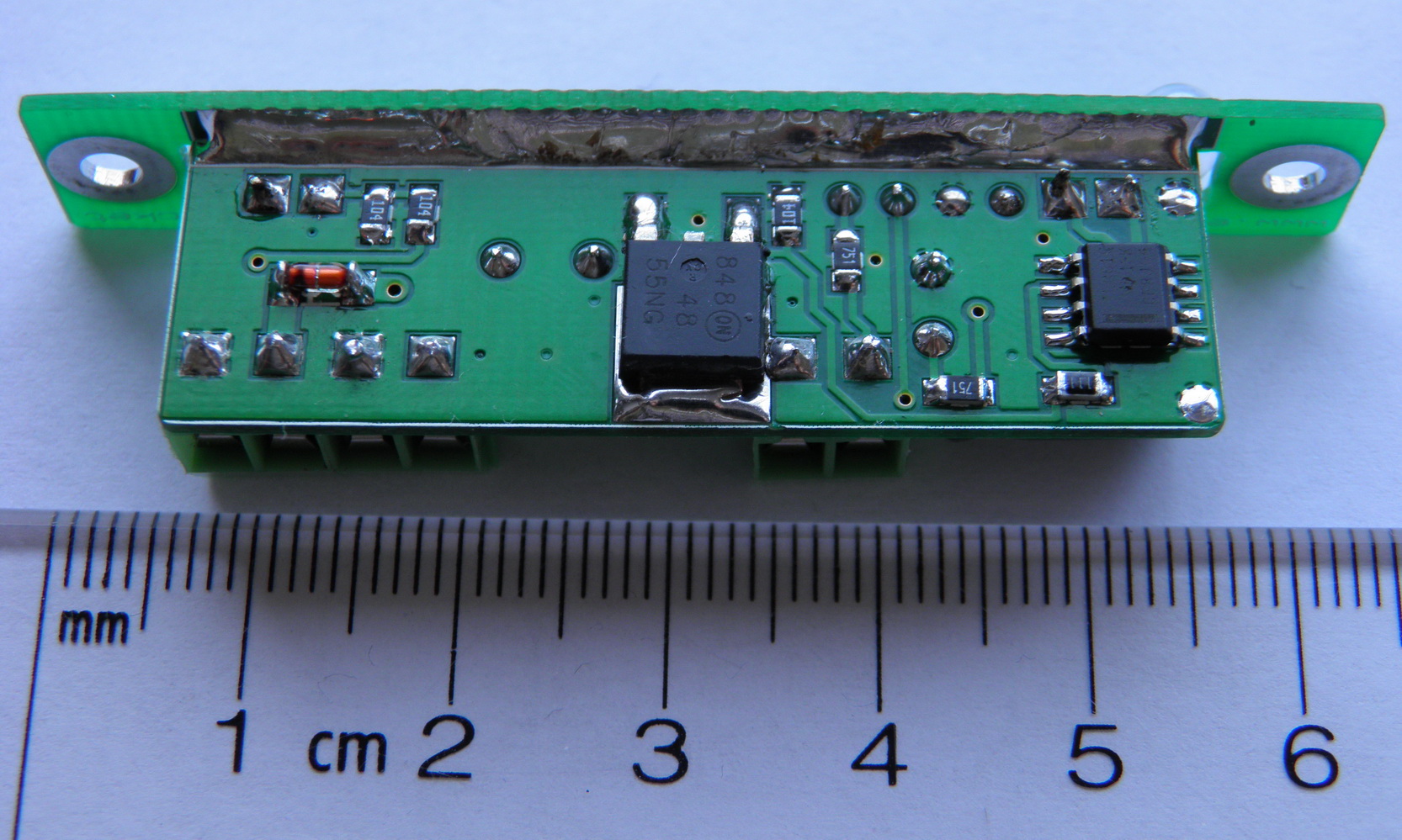
And this is how the “real thing” looks like.


After assembling few test detectors everything works as expected: The bright red LEDs are clearly visible outside under the sun. Although the small igniter detecting MOSFET 2N7002 is hard to work with, it does its job well. The front panel completely covers the opening. And the device switches the load when turning 90 degree left or right as it is supposed.
Final assembly:


In case you want to order printed circuit boards from a PCB supplier you will need the following files.
Pinko this is a wonderful blog site with a ton of very interesting information regarding the flight computers and construction details. I was blown away by your paper/epoxy technique of building the electronic enclosure, what a fantastic way! I build small projects with PIC micros and often had difficulties finding the correct enclosures for it, so thanks.
I have a few questions,
1) What schematic software do you use?
2) What PCB layout software do you use for the 2D rendering?
3) How do you render the 3D rendering of the circuit board, what software used?
4) Is the uC programming done in C language? Will you consider to release it?
4) Does using an external 20Mhz XTAL in your experiments does it looses its accuracy due to shock and vibrations? I hope that its been a great year for you and I wish you a very happy New Year 2015!
Hi bolt59,
I am using BASIC for my projects where I write my own libraries based on protocol specifications and datasheets. For the moment I am not planning to release the complete source codes because of some bad experience with that in the past…
However if you have any particular questions in mind about how a problem or something else is approached in my firmware, I would gladly provide you with the algorithms, so you can adapt them to your programming language of choice.
So far I didn’t find any problem with the crystals in regards to shocks and vibrations. I haven’t made any research regarding that but the few times after tests, when I had to check the crystals with an oscilloscope, they had accurate and stable frequency. Another indirect proof of that could be the proper work of the communication protocols which requires tight timings, hence any deviation in the frequency will cause errors to occur. So even if there was some deviation in the frequency it would have been only few ppm.
Thank you for the good wishes and have a happy New Year 2015 too.