
This is an old project which I have been deferring for a while because I lacked time to finish it. Also I was missing a reliable way to verify the altitude calculation algorithms. Now I finally found some time and a way to test it…
Before I start describing this altimeter here’s some basic physics needed to know for the project. As we know when we go higher in the atmosphere the air gets thinner and thus the atmospheric pressure lower. This decrease in the pressure can be calculated if we know the altitude by using the Barometric formula which takes into consideration the ground temperature as well. For more information about the Barometric formula here.
 where
where
P_b = Static pressure (pascals)
T_b = Standard temperature (K)
L_b = Standard temperature lapse rate -0.0065 (K/m) in ISA
h = Height above sea level (meters)
h_b = Height at bottom of layer b (meters; e.g., h_1 = 11,000 meters)
R^* = Universal gas constant for air: 8.31432 N•m /(mol•K)
g_0 = Gravitational acceleration (9.80665 m/s2)
M = Molar mass of Earth’s air (0.0289644 kg/mol)
Thus we can rework this formula to suit our needs and have an equation for the altitude:

Because I am going to use 8bit Microcontroller and I don’t want too much floating point mathematics in my firmware I will set some predetermined values for C1 and C2 which will ease the work of the MCU:
|
T (Celsius) |
T (Kelvin) |
C1 |
C2 |
|
Tb -10C |
263.15 |
-40484.61538 |
0.1902632 |
|
Tb -5C |
268.15 |
-41253.84615 |
0.1902632 |
|
Tb 0C |
273.15 |
-42023.07692 |
0.1902632 |
|
Tb 5C |
278.15 |
-42792.30769 |
0.1902632 |
|
Tb 10C |
283.15 |
-43561.53846 |
0.1902632 |
|
Tb 15C |
288.15 |
-44330.76923 |
0.1902632 |
|
Tb 20C |
293.15 |
-45100 |
0.1902632 |
|
Tb 25C |
298.15 |
-45869.23077 |
0.1902632 |
|
Tb 30C |
303.15 |
-46638.46154 |
0.1902632 |
|
Tb 35C |
308.15 |
-47407.69231 |
0.1902632 |
Now all we have to do is to find a way to measure the change in the air pressure when the rocket goes up.
Here’s my design of such a device that will measure the atmospheric pressure through Analog-to-Digital converter, store the information in the memory and display the readings on a 4 digits 7LED display.
 The hearth of this altimeter is the PIC18F2553 MCU which has a 12bit built in ADC and USB capability.
Atmospheric pressure is measured by using the Freescale’s absolute pressure sensor MPXHZ6115A which is buffered via a Rail-to-Rail OP AMP.
The 7LED display is CC type but it could be also CA because the common cathode/anode is switched trough the PIC pin (I have included a firmware for the both types).
Each pin of this MCU could handle up to 25mA current and the current through the LED segments is limited by 2kOhm resistors – what means approximately 2mA per segment. The maximum number of segments we can have switched at any time is 8 hence 16mA what wouldn’t be a problem.
Some key characteristics of this altimeter:
– 128Kb EEPROM memory which allows approximately 6 minutes of recording
– 20 record per second
– 4х7LED display
– Displays 1 decimal up to 999m and integer values up to 9999 meters
– Display can be turned on/off for power saving
– USB connector for memory download
– 14 bit ADC resolution trough oversampling
– 70cm per bit resolution
– On the field it will calculate and show the following flight information
– Maximum altitude
– Time to apogee
– Descend time
– Maximum ascending speed
– Average ascending speed
– Maximum descending speed
– Temperature adjustment from -10 to 35 degree Celsius with 5 degree step
– ICSP programming capability
– Four work modes
– Direct – displays the current relative altitude without writing in the memory
– Normal – when the device detects that there is a change in the altitude it will start recording in the memory
– USB – transfers the memory data to computer
– Field – calculates and displays flight information
A complete diagram how each of the modes work.
 Next step was to design a suitable PCb that will fit in the most rockets.
 So the actual altimeter has dimensions of 70×15 mm and weights 11gr


Of course this altimeter wouldn’t work unless the MCU is programmed. So I wrote a firmware for the MCU which is pretty complex because it incorporates several different working modes. Some of the challenges were:
– The 4 digit 7LED display needs to be multiplexed.
– Automatic start detection
– End of the flight detection
– FIFO buffer in the RAM so no data is being lost when it has to detect the start
– Variable display of the decimal value
– Reliable Low-Pass digital filter when calculating data on the field
– USB connection through virtual COM port
– 7LED display can be turned ON/OFF from the firmware
– Displays the relative altitude in real time with 1sec refresh time hence a lot of floating point math
– A lot of menus to be controlled only by 2 jumpers
– Oversampling to get 14bit readings from 12bit ADC
As result the program code is more than 2000 rows and the firmware takes approximately 95% of the MCU’s FLASH memory. Despite the heavy floating point math the PIC18F2553 does well because it works at 48MHz clock. I have uploaded the hex file at the bottom of the page.
Some key electrical characteristics:
– The LDO regulator works down to 0.5v difference thus min 5.5v.
– 31 mA consumption with LED off
– 41 mA consumption with LED on
– 48 mA consumption when the USB is connected
Once I assembled a prototype device and programmed it with the firmware it’s time for testing. In order to test it I need two things – a barometric chamber to control the pressure and reliable calibrated altimeter to compare and verify the readings with.
My barometric chamber was made from a large jar with a tubing trough the cap so I can suck out the air from in it thus effectively lowering the pressure and emulating a rocket flight. In the same time I can monitor the readings through the glass.
As second altimeter I used the JollyLogics’s AltimeterONE which they say on the site has been calibrated in controlled environment.

After the first very promising series of tests I noticed that at low altitudes there were minor differences between my altimeter and AltimeterONE. However when the altitude increased the difference increased from 0% to 1.5% for the range of 0 to 2000 meters, also my altimeter always detected higher altitude. This made me thinking that probably AltimeterONE has been calibrated for a different start temperature.


After downloading the information from the memory and running some simulations in Excel I discovered that there would be only minor difference if I set my start temperature to 20 degrees Celsius (my device allows only steps of 5 degrees) and virtually none if I it is 18 degrees.
Thus I set up the start temperature and ran a new set of tests. The difference was 6 meters for 2km altitude (better than that ca only the GPS ) which proved my theory. So I can make two conclusions:
– The transfer function from pressure to altitude that I am using is correct
– AltimeterONE is calibrated for 18 degrees start temperature – not really related to my projects


Time to check for repeatability thus I assembled few more devices and tested them; afterwards the memory was downloaded to see how in reality the readings look like:


Short video of what flight information will be shown on the field
And finally a test rocket from vega with the altimeter mounted on it.

This altimeter can be used as CDC device and will appear as a virtual serial port in your Device Manager. This way all data can be downloaded through a serial terminal. For this you have to use the CDC firmware.
In order to use it as CDC device you will need a serial terminal, however not all serial programs work so well with virtual COM ports. One program that works is this one. Also you will need CDC drivers which Windows XP and Windows 7 downloads automatically. Further on you will have to manually import all information in an Excel spreadsheet and crunch the data.
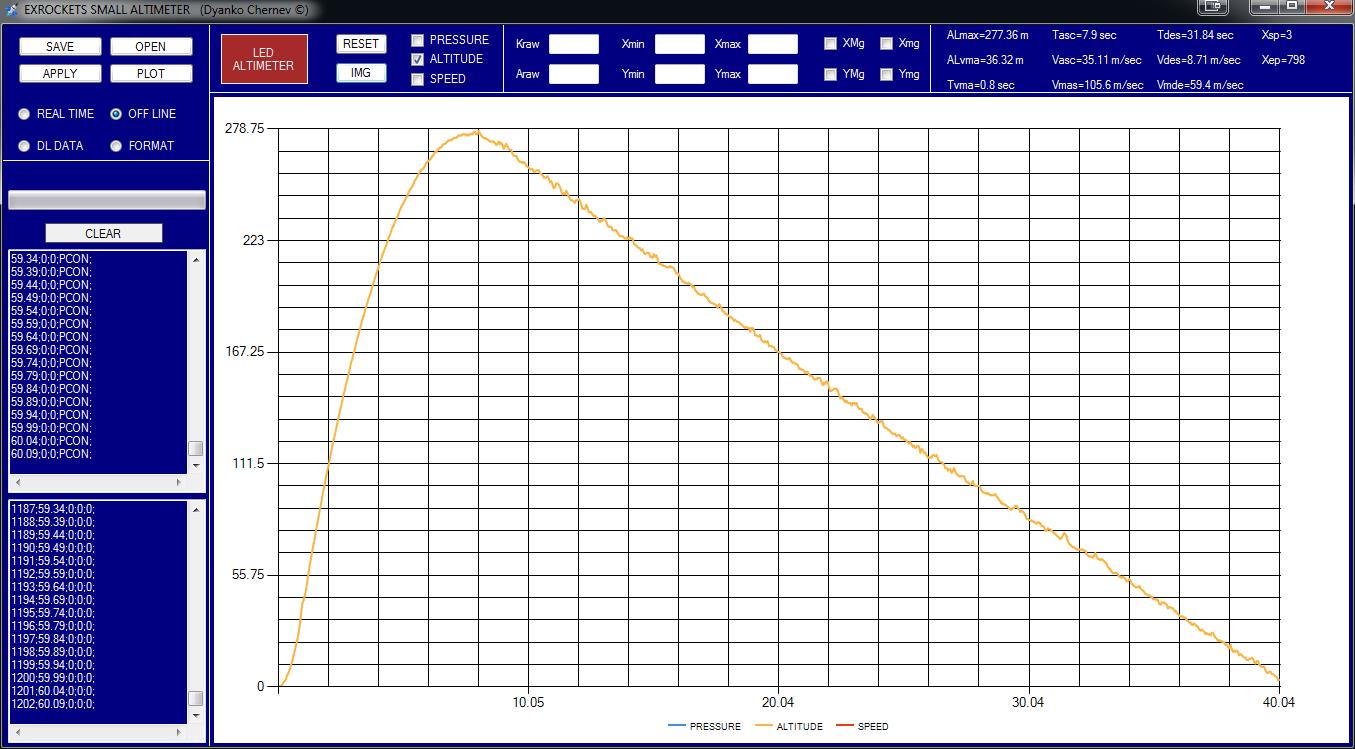
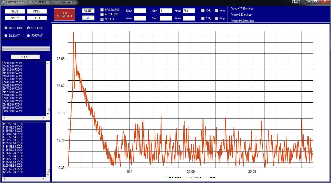
Another option is to use the altimeter as HID device. This have some advantages like universal drivers so windows won’t need to look for new drivers. However you will need software to communicate with the device. For this purpose I have written a program that will do all communication with altimeter and in the same time the program will calculate and visualize the data. In addition you can use it in a Real-time mode to monitor the barometric pressure. Complete HELP can be found inside the archive.
Also this program can be used to crunch data from other altimeters – for more information see the help file. The program can be downloaded from the bottom of the page together with the new HID firmware needed to support the program.
Some screenshots:
MCU FIRMWARE HID CC (hex file)
MCU FIRMWARE HID CA (hex file)
MCU FIRMWARE CDC CC (hex file)
MCU FIRMWARE CDC CA (hex file)
PCB MANUFACTURING FILES (Gerber files)
ALTITUDE vs TEMPERATURE SIMULATION (Excel file)
EXROCKETS_LED_ALTIMETER_v_1_00.zip
Hi, is it possible to order one of these?
Thank you for your interest! Unfortunately I don’t make units for sale.
I would like to build one of these to measure the flight of my rocket and putting the measurements afterwards on my computer. Do you know how I can add something to this construction so that I can save the measured measurements?
Thanks for your reply