 I had few MEMS accelerometers around and thought it would be nice idea to be able to measure the acceleration during the rocket flight.
Why is it good to know the acceleration – well it is fun to brag about how many g’s you rocket experienced :). Of course I had more scientific intentions:
- if I know the acceleration during the burn-out, the weight of the rocket and the weight of the propellant then I can derive the thrust my motor produced with a good approximation.
- further if I know the characteristics of your motor I can compare them with the one measured during the flight.
- knowing the statically measured thrust and the dynamically measured one for known propellant could give me a good idea for the drag coefficient of the rocket. *
- if I know the drag coefficient then I can study some characteristics of unknown fuels that might have significant difference between the dynamic and static testing (good example is the Zinc-Sulfur rocket propellant)
- I can precisely measure the burn-out time
- combined with the small altimeter it can be used to enhance the both readings (remember the velocity-acceleration-distance-time relationships)
*For example the thrust that a potassium nitrate sugar motor will produce doesn’t differ whether measured dynamically or statically.
Once I determined the benefits and the need of an accelerometer on board it’s time for some fun in the electronics domain.
Because I already designed similar as functionality altimeter there was no need to reinvent the wheel.
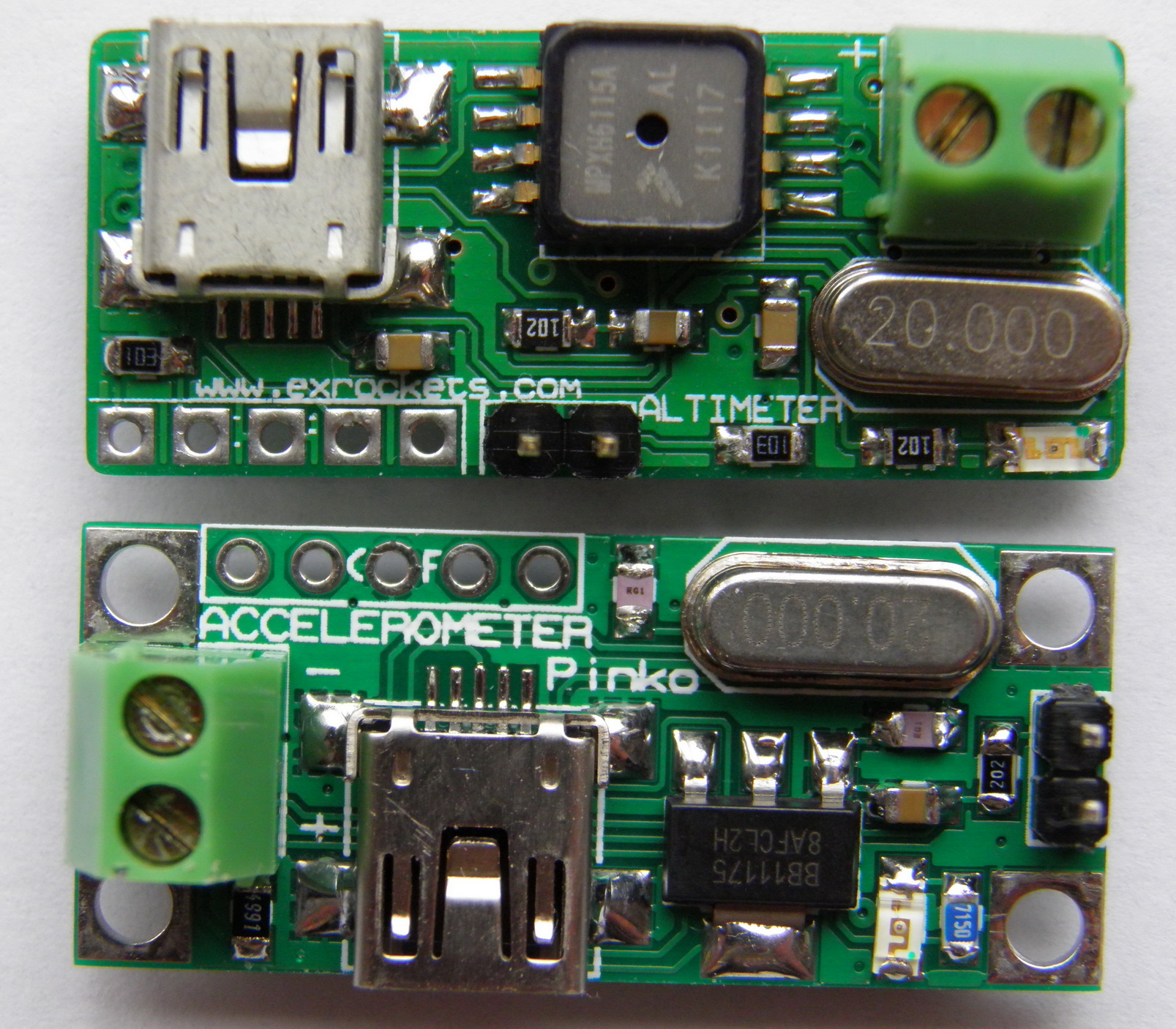
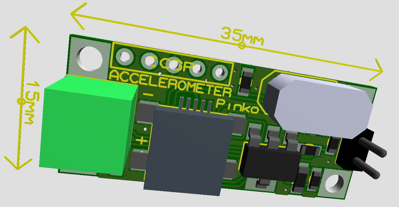
Basically what I did was to take small altimeter and to change the pressure sensor with a MEMS sensor that measures acceleration. Thus the new accelerometer has the same size as the altimeter.
Top: Altimeter Size: 35m x 15mm
Bottom: Accelerometer Size: 35m x 15mm
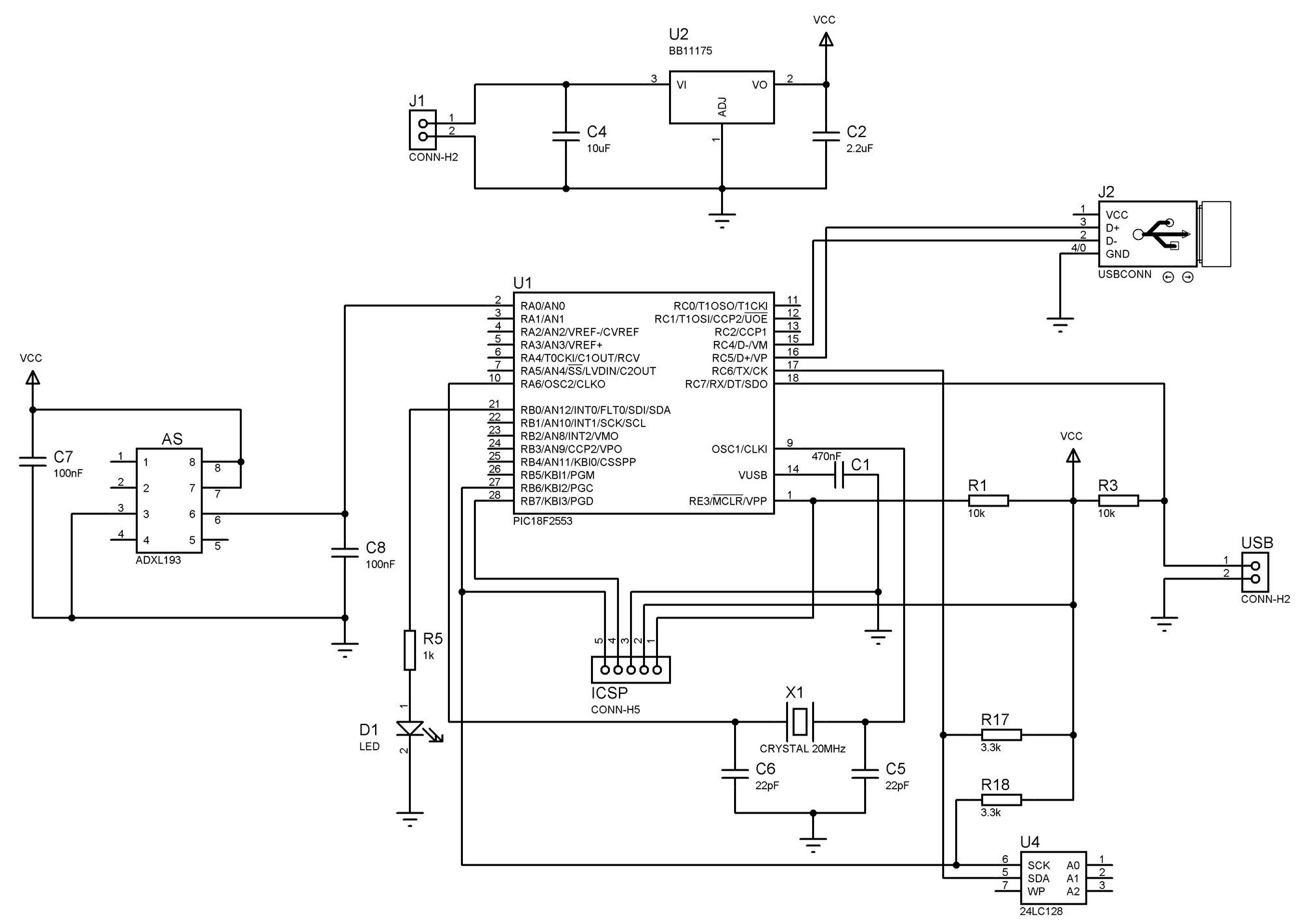 The MEMS sensor I had at hand is ADXL193 which is 1-axis +-120g sensor. It would have been much better if I had +-50g sensors but I am working with spare parts so this one had to do it. Once the electrical diagram was drawn it was time to rearrange the components to better fit the new sensor:
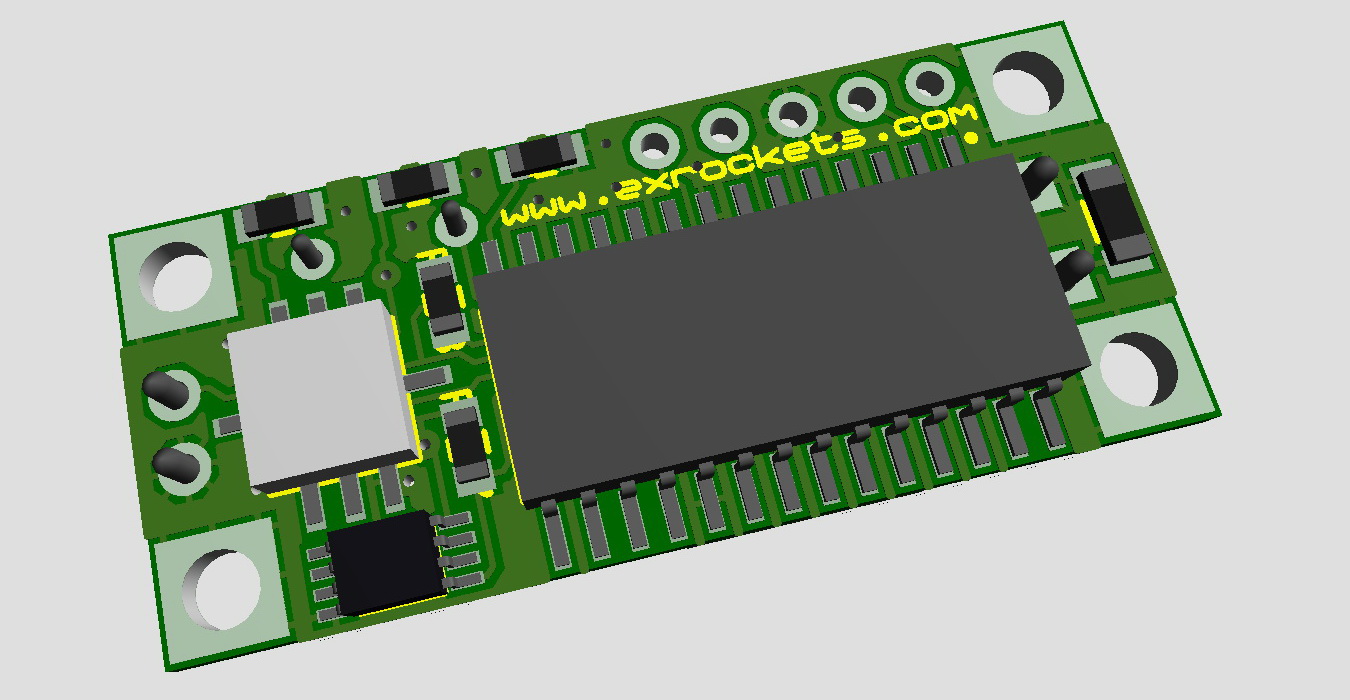
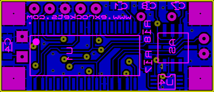
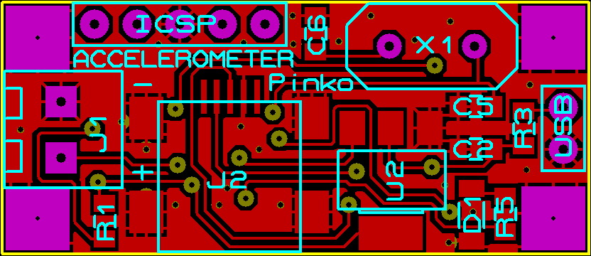
And here is the new PCB design:
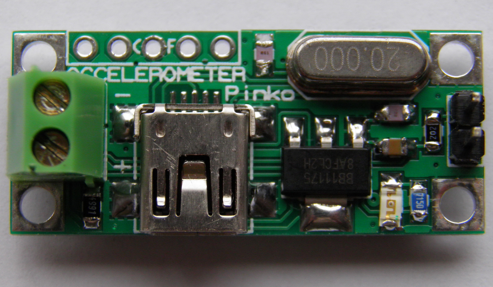
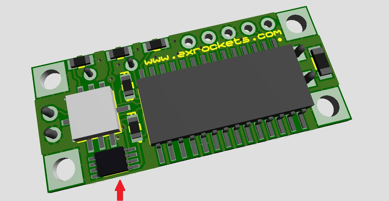
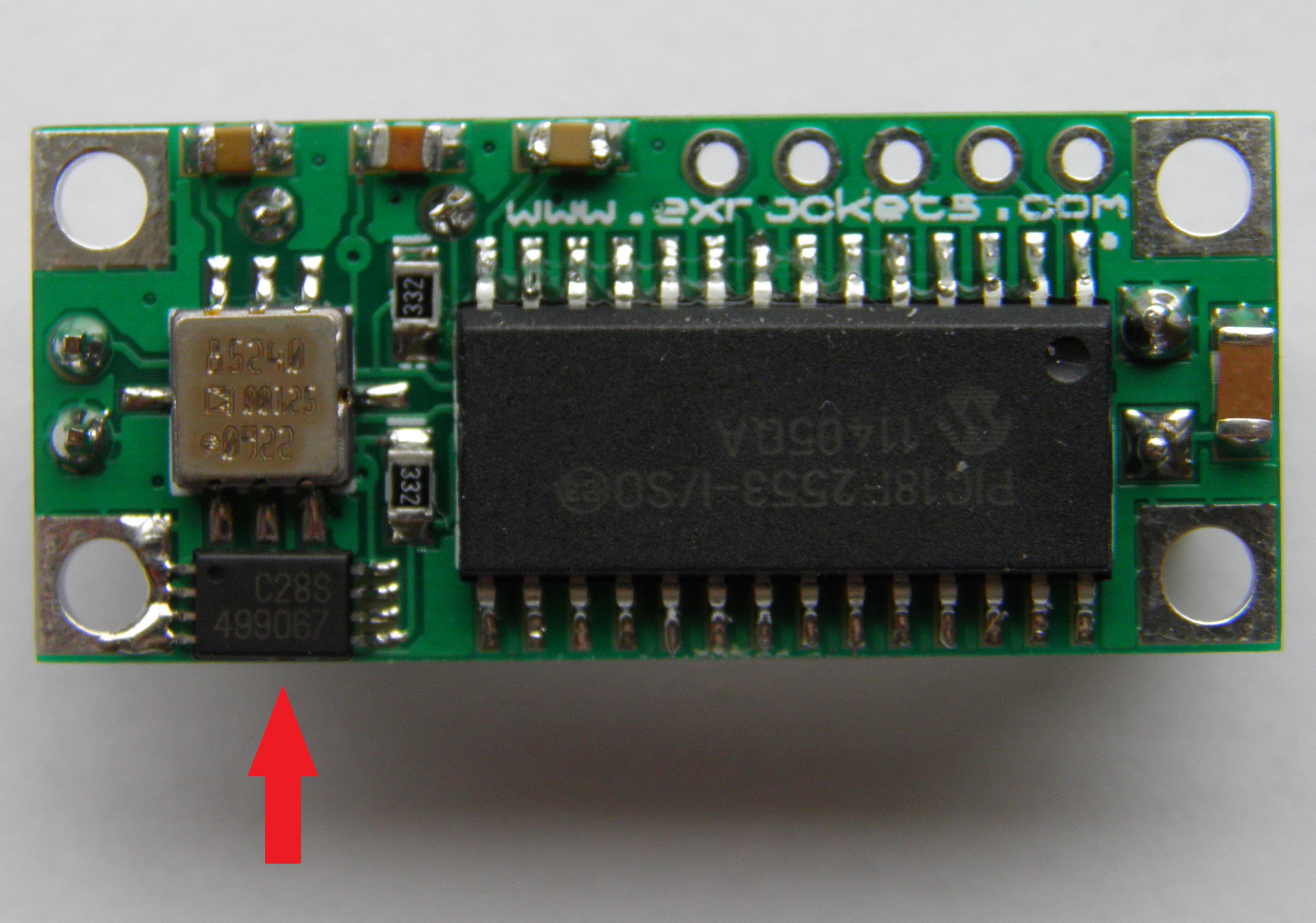
Finally the accelerometer itself assembled:
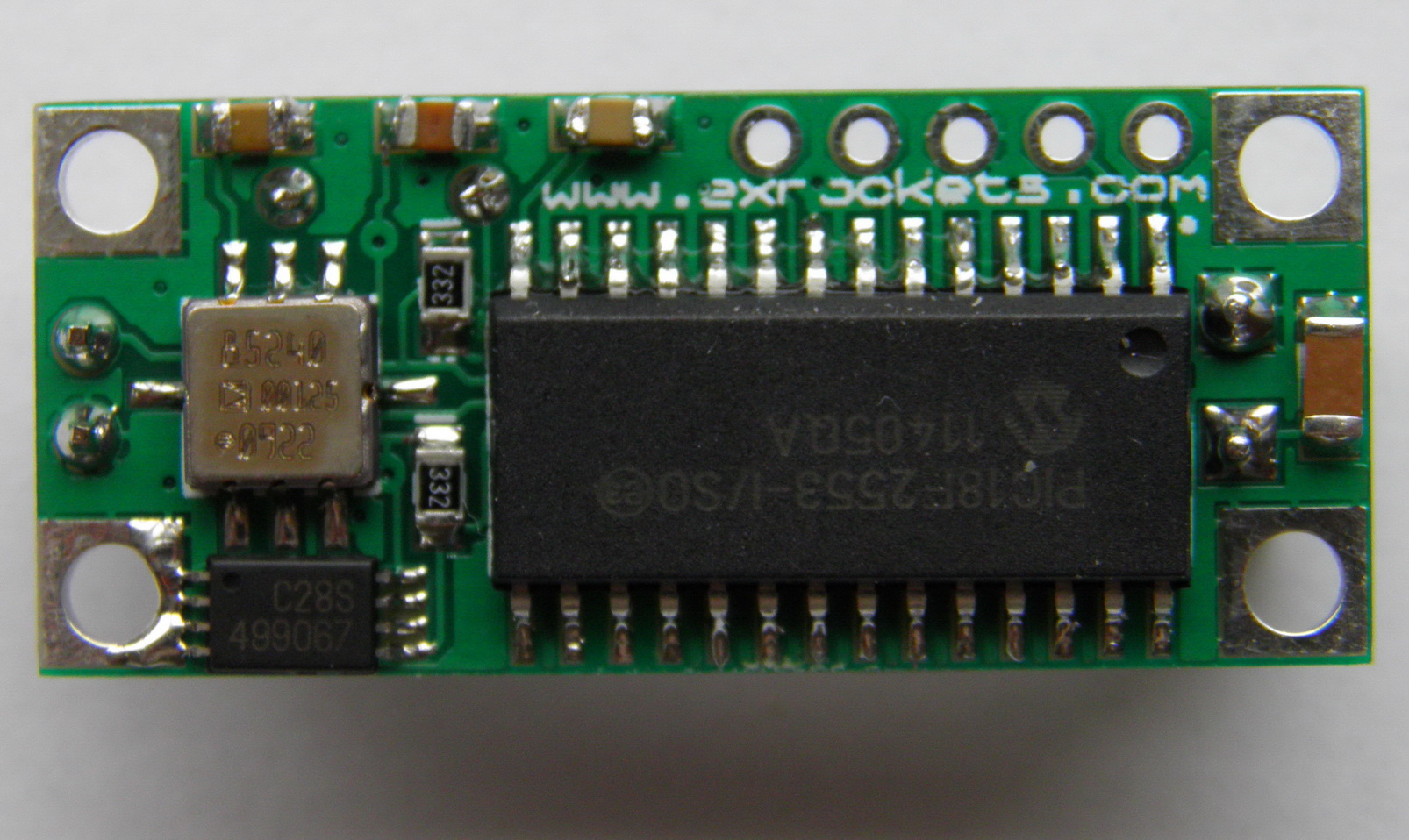
Once I started the assembling I noticed that I made a little mistake – the package for the EEPROM memory that I used for the design was a little different from the one that I have at hand. However this wasn’t such an issue because all pins 1 to 4 have to be grounded anyway – so the “problem” was resolved immediately.
It is time to write the firmware for the MCU. Again it is based on the one that I wrote for the small altimeter with minor changes. This time I implemented much higher oversampling rate and averaging in order to increase the resolution to 14bit ADC and to lower the noise levels for stable readings. Some of the futures include:
– 128Kb EEPROM memory which allows approximately 6 minutes of recording
– 20 record per second
– USB connector for memory download
– 14 bit ADC resolution trough oversampling
– 1 g calibration option (explained further down)
– ICSP programming capability
– Auto start detection
Complete diagram how each of the modes work.
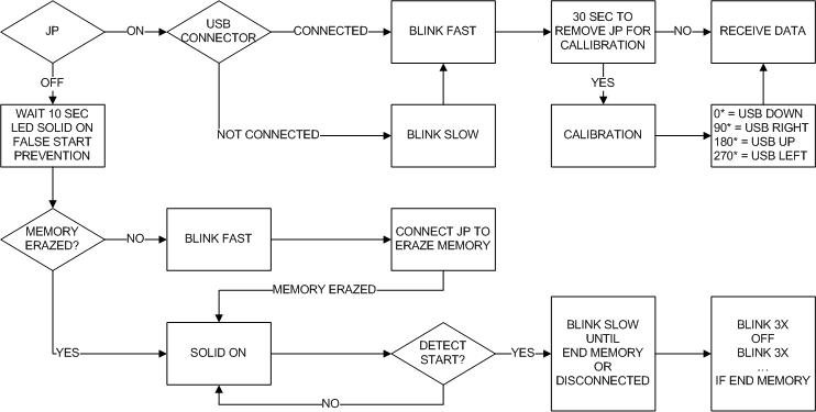
The firmware automatically detects the rocket start – the way how it does it is to check for acceleration changes in 4 consecutive readings by using a circular buffer. As soon as it detects the start, the MCU also starts recording the readings in the memory so there is not enough time to write the initial buffer as well. That’s why the buffer is being transferred once the sensor detects no motion in 2 seconds or if the max record time is exceeded, which is not a problem in real-flight conditions. These initial values are important for measurement correction in case the rocket’s start position wasn’t perpendicular to the earth surface (correction to 1 g ).
Bottom-line if you do a manual test by simply shaking the accelerometer, you will have to leave it for two motionless seconds, to write the initial readings.
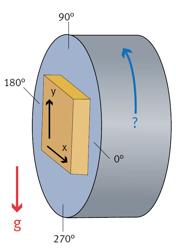
As I mentioned this accelerometer has the option for 1 g calibration – this is a particular challenge for high g sensors because of the slightest misalignment will give significant error when low ADC resolution and noise are present. Also all sensors have some offset that will affect the readings. Fortunately noise and low ADC are not such a problem due to the high oversampling and offset can be measured and accounted for.
The calibration itself is not complicated at all – all you have to do is to rotate and position the sensor in the four directions as indicated – at 0o, 90o, 180o and 270o.
Communication is done through the USB interface where the user is given instructions what to do and the MCU will measure the readings. Consequently through some mathematical transformations the firmware will derive a linear equation that will take in account the offset and the ADC to g transformation coefficients.
If you are interested in more details how exactly this is done you can see MEMS ACC CALLIBRATION.pdf at the end of this post.
One other way for calibrating accelerometers is using the centrifugal force to simulate linear acceleration. Basically if you know the exact rotation speed and the distance from the center you can calculate the acceleration experienced by the sensor, however this is much harder to be done at home. Still it is a good way to test the accelerometer. So I used a 2 meters long rope with the sensor at one end and me holding it at the other end. Then I started spinning the rope as fast and uniformly as I could while counting the revolutions I do for one minute. My calculations and the acceleration measured were reasonably close.
Here’s one test start done by -vega- who was very kind to send me the log files.
This rocket motor has already been tested and measured on the ground and has well known characteristics, so it would have been good idea to know how does it perform during a flight? From the following two graphs – first one is the ground test and the second one is the flight test. The thrust profile and the burn-out time are almost identical.
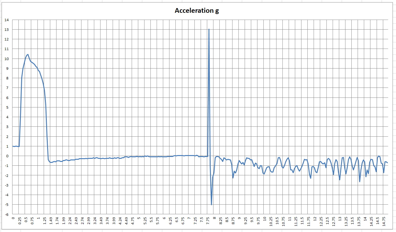
This rocket had an altimeter and one accelerometer and this is the altitude and acceleration measured during this test.
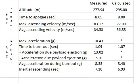
Finally it would be nice to see how does the motor and the rocket perform compared to the predicted flight characteristics. The flight’s expected characteristics were calculated with Richard Nakka’s EzAlt – Rocket Flight Performance Spreadsheet.
This accelerometer can be used as CDC device and will appear as a virtual serial port in your Device Manager. This way all data can be downloaded through a serial terminal. For this you have to use the CDC firmware.
In order to use it as CDC device you will need a serial terminal, however not all serial programs work so well with virtual COM ports. One program that works is this one. Also you will need CDC drivers which Windows XP and Windows 7 downloads automatically. Further on you will have to manually import all information in an Excel spreadsheet and crunch the data.
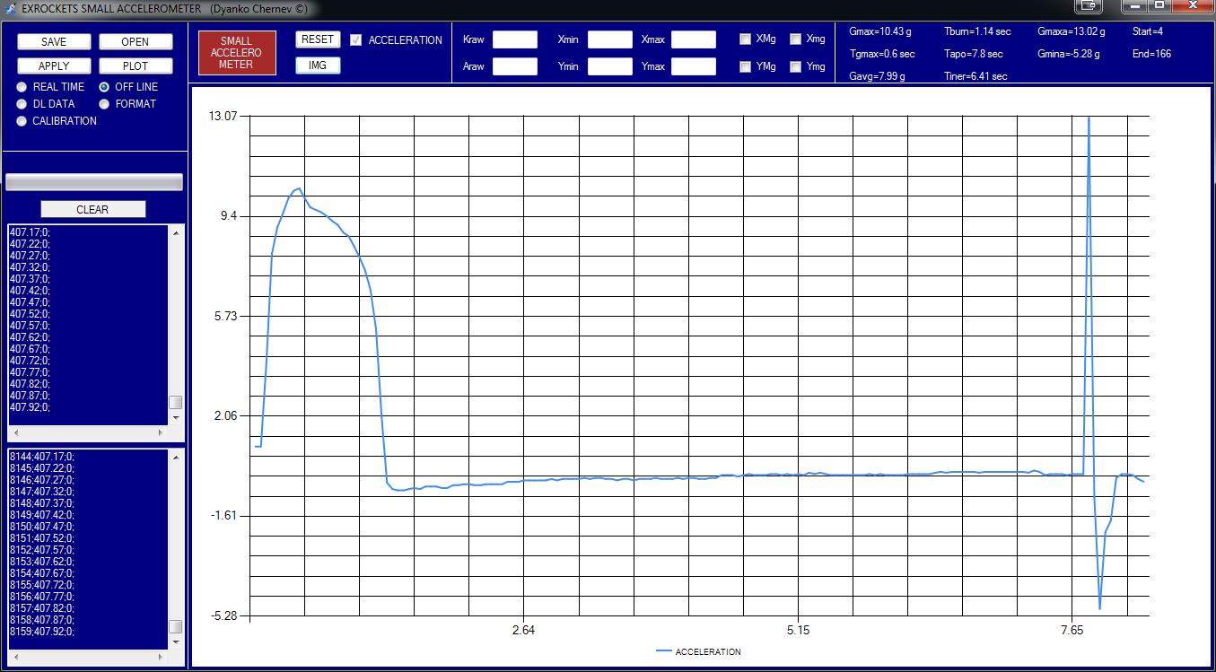
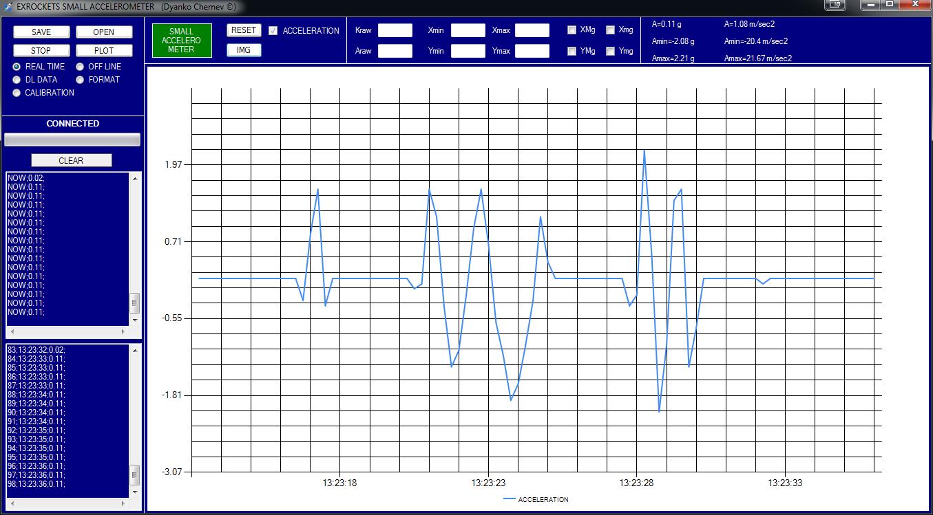
Another option is to use the accelerometer as HID device. This have some advantages like universal drivers so windows won’t need to look for new drivers. However you will need software to communicate with the device. For this purpose I have written a program that will do all communication with this accelerometer and in the same time the program will calculate and visualize the data. In addition you can use it in a Real-time mode to monitor the acceleration in real time. Complete HELP can be found inside the archive.
Also this program can be used to crunch data from other accelerometer– for more information see the help file. The program can be downloaded from the bottom of the page together with the new HID firmware needed to support the program.
Some screenshots:
MCU FIRMWARE HID v1.01 (hex file)
MCU FIRMWARE CDC v1.04 (hex file)
PCB MANUFACTURING FILES (Gerber files)
EXROCKETS_SMALL_ACCELEROMETER_v_1_01.ZIP
MEMS ACCELERATION SENSOR CALIBRATION
Leave a Reply