Update Note: As mentioned the SD card should be 2GB or less and formatted as FAT16. Due to addressing restrictions the SD card should contain only one partition, created as PRIMARY PARTITION with no unallocated space before the partition. Please note that some SD cards come with partitions, created as logical partitions and need to have their partitions recreated as mentioned previously.
Some time ago I decoded to make a simple general purpose Data Logger with the following parameters for the project.
- it should have very simple design that should be doable by most amateurs
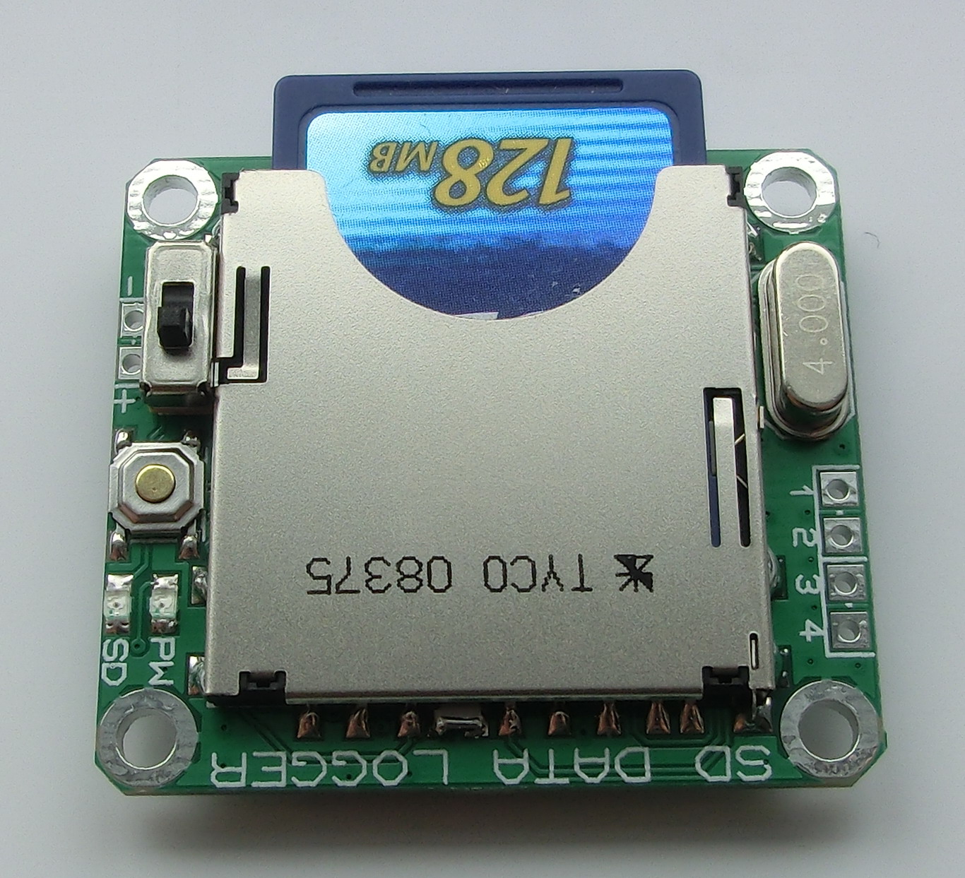
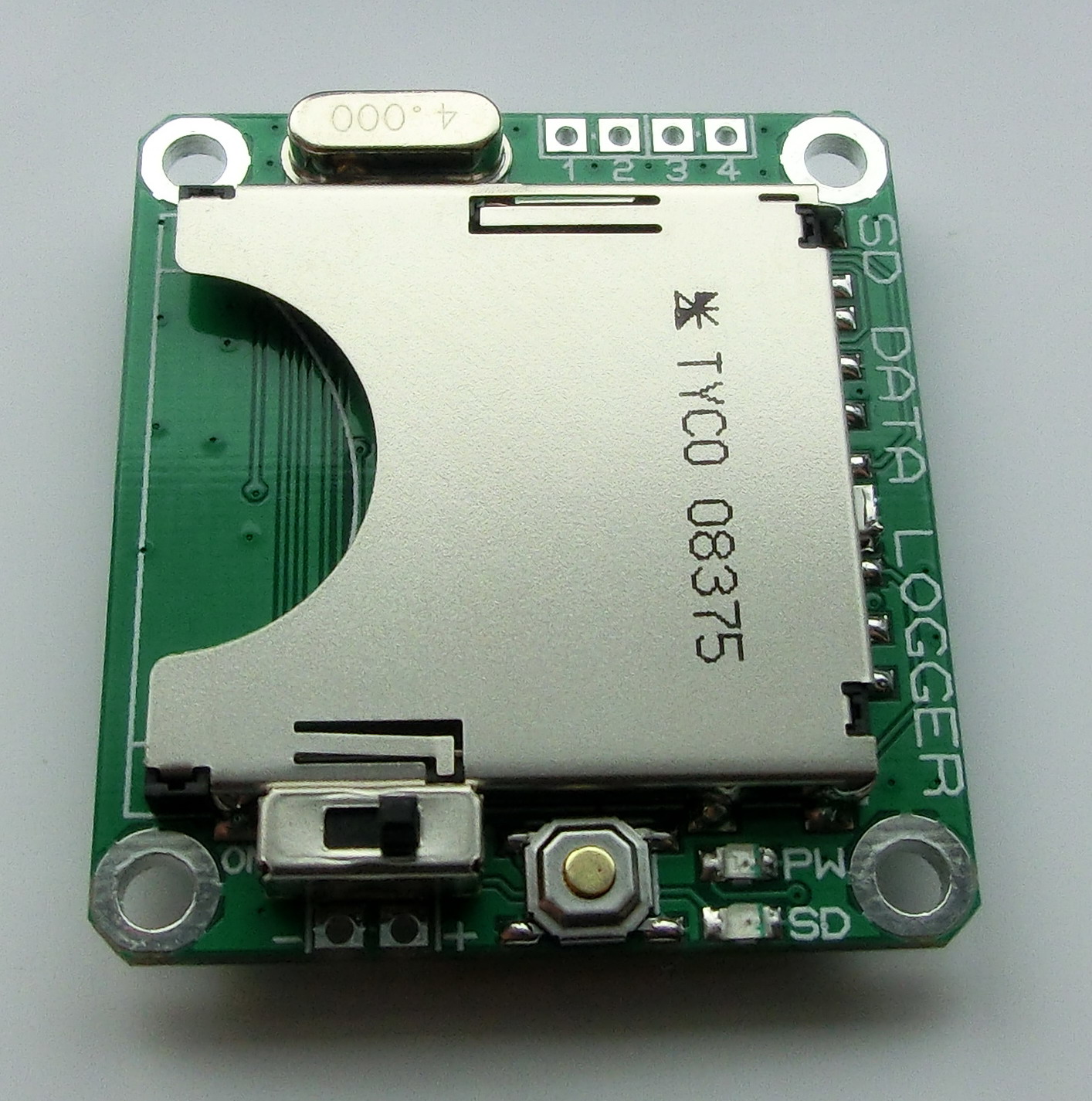
- the Data Logger should write the data in a SD memory card in simple text files
- minimum 2 ADC channels
- simple to use and simple settings
- energy efficient
- low cost
I think I managed to fulfill all my requirements and the prototype is quite good. So I am going to describe the design and also I am attaching the firmware for anybody who wishes to make his own Data Logger.
it should have very simple design that should be doable by most amateurs

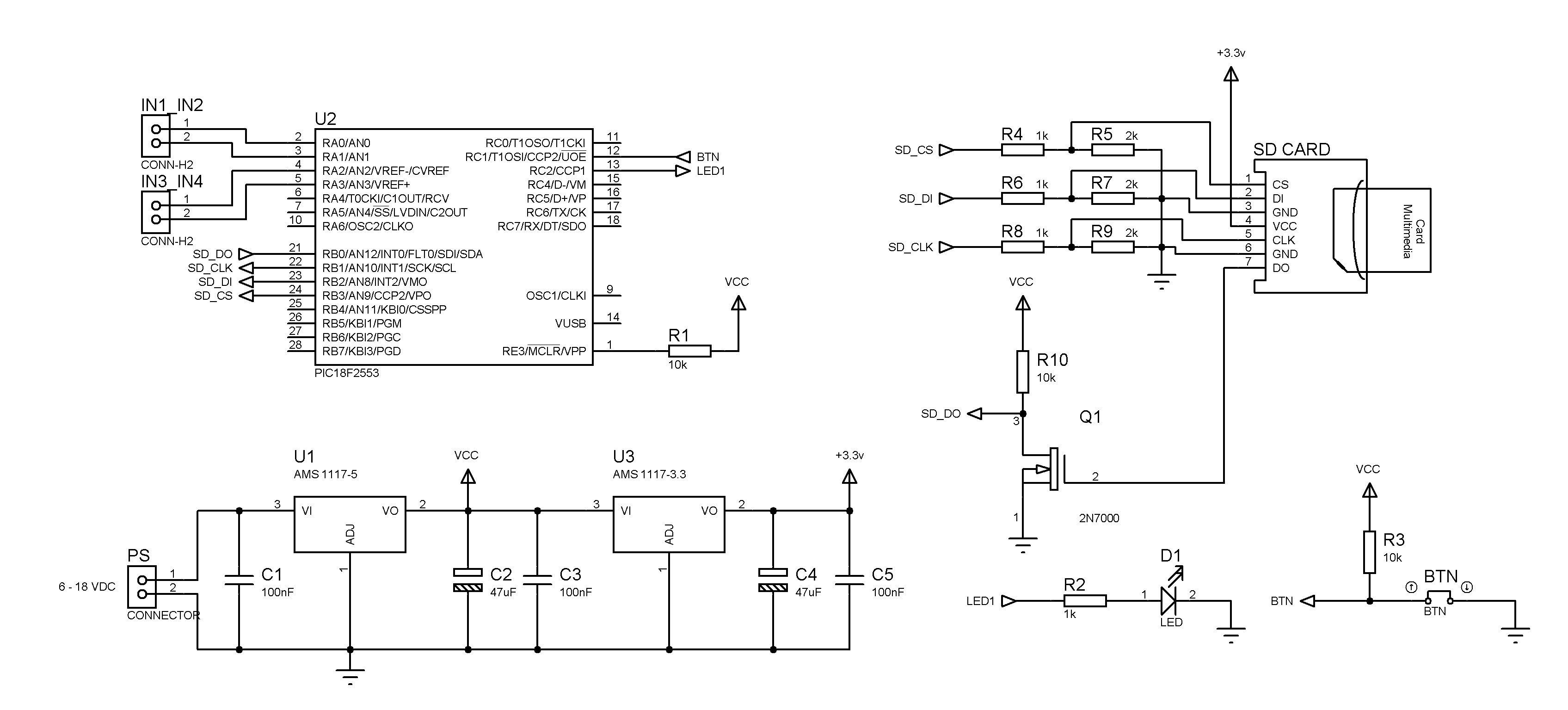
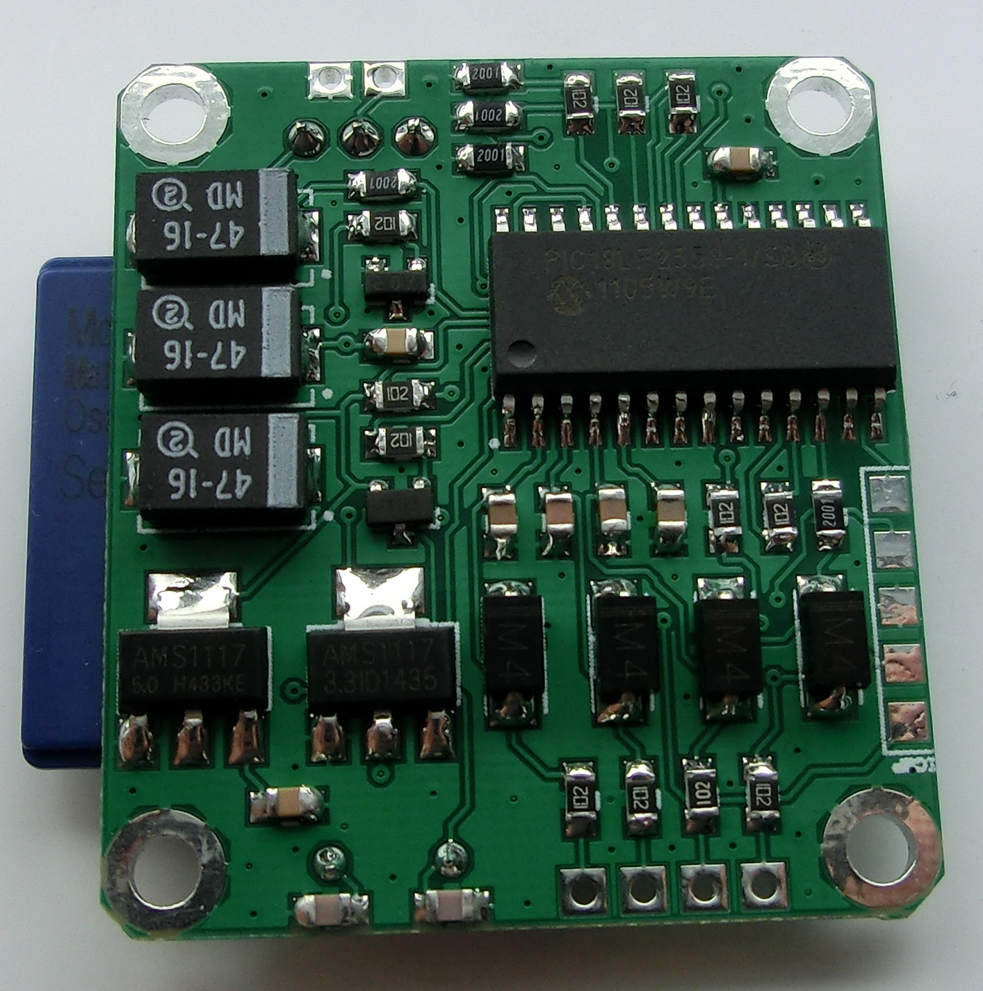
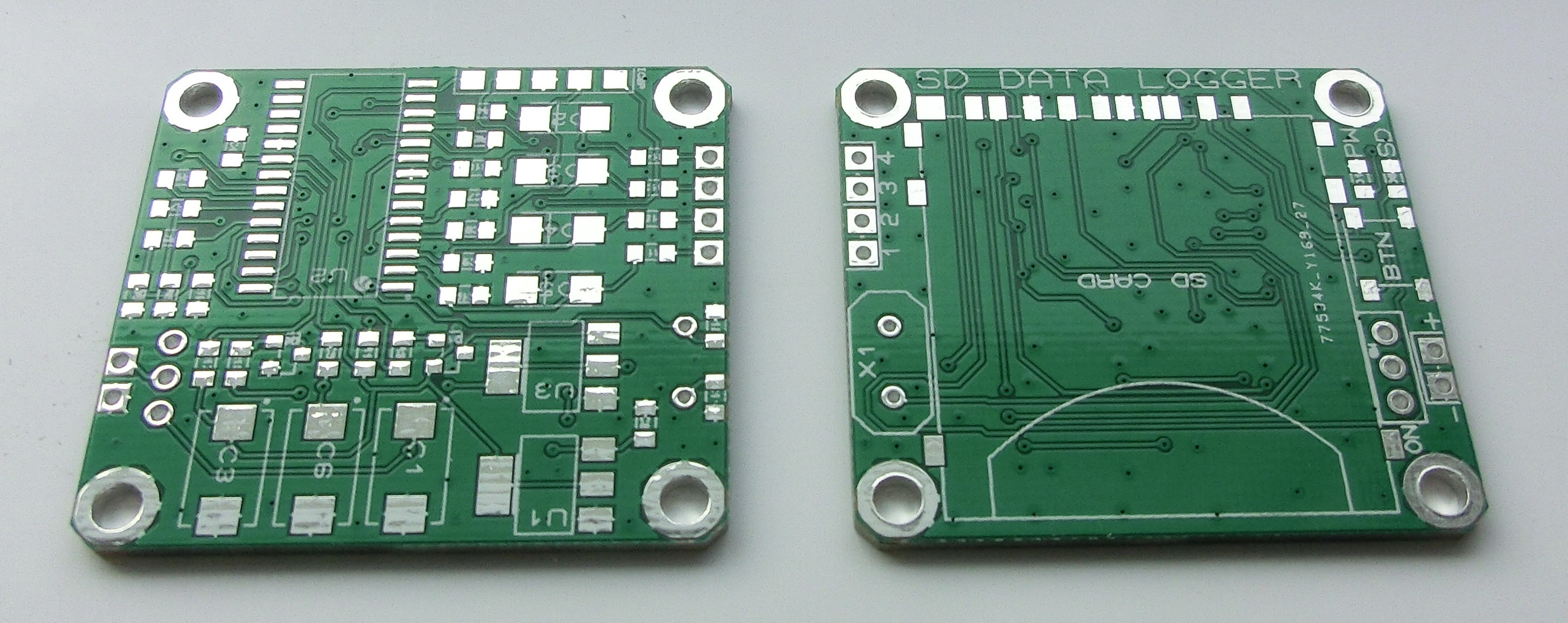
The both schematics represent the same design but the second schematic has only the bare minimum of components for the proper functioning of the Data Logger. All components are available at most electronic stores in standard DIP sizes which are easy to assemble.
In the second schematic what is missing is the power supply LED diode. Also the P-channel MOSFET, which switches on and off the 3.3v regulator is missing, so the 3.3v power supply is always on. I removed the four ADC input low-pass filters and the protecting diodes. So if you are not using those diodes you should make sure that the input signal doesn’t exceed 5v or you are risking damaging the PIC microcontroller.
The power supply consists of a 5v and 3.3v rails. The 3.3v rail powers the SD memory card. You can use any 5 and 3.3v voltage regulators or other solution but keep in mind that according the specifications the SD memory cards can draw up to 200mA depending on the models.
the Data Logger should write the data in a SD memory card in simple text files
This Data Logger works with SD memory cards, formatted with FAT16, hence the maximum card size is 4GB.
The firmware keeps record of the total number of completed tests/records and assigns new serial number to the next test/record. At the beginning of each record, the Data Logger creates two new text files in the SD card. The first one is D_x.TXT (x = test serial number) which will hold the ADC readings from the four channels. The second file is S_x.TXT (x = test serial number) which will hold system status information like events and/or errors during the test.
If any of these files already exist, they will be appended and not deleted.
minimum 2 ADC channels
The Data Logger has four 12b ADC inputs
simple to use and simple settings
To set up the Data Logger all you have to do is to create a text file called ADC.TXT and copy it in the SD memory card. This Data Logger set up parameters should be written at the beginning on the first line of this file and should be separated by a semicolon – for example “100;200;0;”.
- The first parameter is the sampling time, which is expressed in milliseconds. The minimum sampling time is 5ms (200 samples per second) and the maximum is 99999999ms. In this example the time period between sampling the inputs is 100ms.
- The second parameter is the total number of samples to be taken. “0” means no limit. Otherwise it could be between 1 and 99999999.
- The third parameter is the energy conserving mode. “0” switches is it off and “1” switches it on. If the sampling time is less than 30sec, this parameter will be ignored. See further down for more detailed explanation.
The logical flow chart:
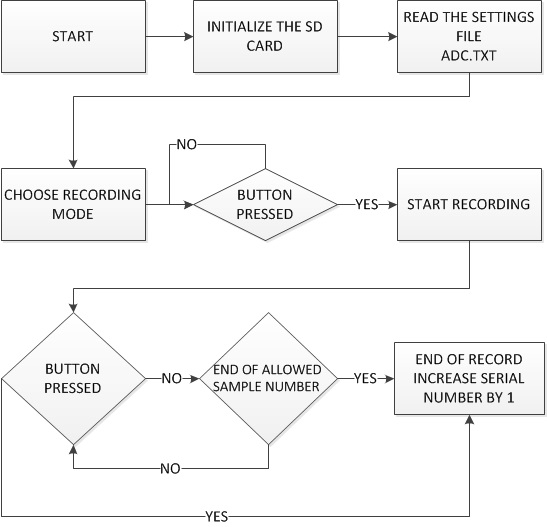
– After powering on, the Data Logger will check if the SD card is inserted and everything is OK with the card. It will also check the settings in the ADC.TXT file. If there is a problem then the SD LED will stay solid on. If there is no problem the SD LED will blink several times while reading and creating the new files on the card and will turn off showing that the Data Logger is ready to start the data recording.
– Press the button to start the data record. While using the SD memory card, the SD LED will blink showing that it is unsafe to remove the card or to power down the Data Logger with risk for damaging the currently used data files. If the SD LED is off then it is safe to power down the Data Logger or to remove the SD memory card.
– Press the button again at any time to stop the data acquisition. If the total allowed number of samples has already been taken then the Data Logger will power down and all future command will be ignored until you reset the power.
*At any time: If the SD LED stays solid on this means that there is a problem either with the card or the settings. For more information check the corresponding file in the memory card.
** The PW LED will always turn on for 100ms every 4 seconds (short blink every 4 seconds) indicating that the power supply is ok and the microcontroller is working properly.
energy efficient
The total energy consumption depends on both the SD memory card and the Data Logger. While I have no control how much current the memory card will draw I have control on when it will be switched on and the speed of the Data Logger so I came with the following three power schemes.
- If the sampling time is less than 2 seconds, the Data Logger and the memory card are always on. The Data Logger consumption is about 20mA and memory card depends on the model.
- If the sampling time is more than 2 seconds, then the Data Logger is always on and the SD memory card will be switched on for about a second only when new data is to be written. The rest of the period the SD card power supply is switched off.
3. Energy conserving mode (if the sampling time is less than 30sec, this parameter will be ignored) – between every data record the SD memory card will be switched off and the microcontroller will stop using the crystal resonator while using the lower speed internal resonator. The higher speed crystal and SD memory card will be switched on only for about a second every time a new sample is taken and has to be written in the memory card. This will allow the total consumption to be as low as 5mA during samples. However there is a tradeoff. The internal oscillator is factory calibrated but it is much more temperature dependent than the crystal. The factory calibration is done for 25 degrees and depending on the external temperature this could result in +-5% timing deviation as opposite to the 0.002% if the crystal resonator is used all the time.
low cost
In my design I used common parts that can easily be found in most electronic stores and the total cost is about $6 to $8. The only thing is that you will need a DIY or off-the-shelf PIC programmer to flash the firmware. However if there is a need, a simple PIC programmer (6-8 components) can be made from few spare parts and using the PC serial port you can program the microcontroller.
This Data Logger can be made from DIP size parts and on any prototype board but I decided to draw a new SMD PCB for the project. I am attaching the PCB GERBER files, as well as the MCU firmware and few sample files with the settings, status and data information.
SIMPLE_SD_DATA_LOGGER_FIRMWARE.ZIP
SIMPLE_SD_DATA_LOGGER – CADCAM.ZIP
ADC.TXT
D_0.TXT
S_0.TXT
ADDITIONAL_FIRMWARE_2520_2550_2580.ZIP
I love this. This is so simple and even elegant in design. Nice compact little module. Is it possible to get a copy of the project? I am trying to build something similar for a project I am working on to log data from my refigerator/freezer, but I am using 9 thermocouples and the data will be sent via spi to the controller. If I could look at your sourcecode I could probably modify it to do what I need.
You’r so far is the only working module I have seen that comes close to dong what I am trying to accomplish.
Hello Tim,
my projects are free to use but unfortunately not open source.
Regards
Would you be open to compensation? In other words, could I pay you for it?
Hello Tim,
I appreciate your offer but I am writing my own libraries and for the moment I am not ready to share them.
Regards
P.s. However if you are really stuck, you can send me an e-mail through the contact form with a description of what you need and I might be able to modify the source code and compile a new hex file to suit your project (although I can’t guarantee a time frame).
recompile firmware for 2520/50/80 and ext Vref. plz.
Hello Alex,
basically this means 10b ADC and Vref+ at RA3/AN3 (pin 5). Would you like me to move the CH4 on RA5/AN4 (pin 7)?
Regards
pinout does not matter. thx.
/perfect way – selection of the number of channels via the config
Hello Alex,
the firmware was recompiled and is available for download at the bottom of the page. The changes are minor and there should not be a problem with those controllers. I didn’t check the firmware because this will require desoldering (I am using SOIC package) the current chip on my PCB.
However if there is a problem, let me know and I will see to test it.
(2550) it’s work. but adc ch3 remapped to ch6 it’s bad.
What do you mean by ch6?
– PortA.3 (i.e. AN3) is now the Vref+
– the fourth input is now PortA.5 i.e. AN4
I rechecked, yes it’s true, but Proteus complains of attempts to include also AN6. it is not critical but…
thank you all the best
Hi!
Would it be possible to have firmware that records a 9,600 baud stream from the serial port? This would be useful for GPS, voltmeters, etc.
Hello Brian,
this wasn’t the initial purpose of the devise but I was asked by other people to do the same modifications. The changes are not significant but I have to test the new firmware – I will see to it in the next week or two when I have more time.
Hi pinko,
Thanks for providing your project for free.
I have built this but I have problems with the SD-card parts. May I ask the type of the card socket that you used? (TYCO 08735 tells nothing to Google..) Mine is from eBay and while the outer dimension + pad pattern is exactly the same as yours, I suppose the pinout is different…
Hello,
The SD card sockets from Ebay have the same pinout as the one that I used.
Right, thanks for it.
I was confused because the socket has 11 pins (SD-Cards have 9 pins), while all over the internet I only found pinouts with 9 pins.
I had to ‘autopsy’ a victim socket to reveal the function of the remaining 2 pins: the 4th & 5th shorted by the card when inserted, the last one is connected to the metal house when the card is inserted.
Anyway, my circuit has problem with the card (SD is solid on, power is blinking in every 4 secs), so it looks like I need to check signals with a logic analyzer…
Check if this was done:
– using your computer you have to format the SD card in FAT16, thus you will need a SD card of 2GB or less.
– then download and copy the ADC.TXT (keep the capital letters – this is important) file on this card.
– if this works you can modify the ADC.TXT according your requirments.
Pingback: PIC SD CARD DATA LOGGER - Electronics-Lab
your pcb layout is art!
well done on this project, i like it a lot.
Очень крутое изделие. Поздравляю.