
Basics:
There are two main principles that this device is based on – the Earth’s albedo (reflection coefficient) and the fact that LEDs can generate current from light.
The further described device works by measuring the Earth’s albedo. This reflection coefficient is being determined as the ratio between the energy reflected from the Earth’s surface to the total energy received from the Sun.
 (image source http://www.climatepedia.org/Albedo)
This apogee detector actually measures the reflection coefficient by comparing the light coming from the sky with the light being reflected from the Earth and depending on its magnitude we can determine the actual position with respect the earth-sky plane. It is worth mentioning that the Earth’s albedo is different for the different wave lengths. At UV wavelengths the surface albedo is often low compared to longer waves, some 3-8% (but snow can increase the surface albedo up to 95%) with an average of 30% for the visible light spectrum which makes the UV LEDs an obvious choice.
The second principle is that LEDs can not only emit light when current is being applied but they also can be used as photovoltaic cell and they can generate electricity from light. Another important quality of the LEDs is that the emitted light has a specific length and also as photovoltaic cell they are most sensitive to the same wave lengths. Otherwise said a green diode for example will generate the largest current when being lit up with green light.
A thorough research in that matter and more information about the interdependency between the LEDs, the wave length and the current generated, could be found in the following two documents – courtesy of a_centaurus.
LED SPECTROSCOPY
MEASUREMENT LED’s SPECTRAL RESPONSE
Early development:
-VMK- , a member of the Bulgarian experimental rocketry community, proposed few years ago that by using the Earth’s reflection coefficient we can determine when a rocket reaches its apogee. So he designed a prototype with two photo-transistors pointing at different directions (sky and earth). This way we can determine that the rocket is at apogee when it turns upside down and the upper transistor starts looking down to earth. After some discussion and testing Serge77 from the Russian rocketry forums suggested that using UV LEDs instead of Photo-transistors might be more suitable for the purpose because the UV light coming from the sky is much stronger than what is being reflected from the Earth’s surface. Later on it became clear that the minor currents generated by the UV LEDs require highly sensitive comparators in the 1-10 pA range. After some technical difficulties metero (also member of the Bulgarian rocketry forums) proposed a particular technical solution and -VMK- drew the first working schematics which all later development is based on.
 The original design is on the picture.
Later with the -VMK-‘s permission, I modified the design by adding some functionality and choosing new, more common, components as shown on the following schematic:

U2 is a FET OP AMP TL051/TL061 which has a low input current and it is also a cheap choice. This OP AMP works as comparator and compares the current between the two UV LEDs. Once the rocket reaches its highest point it will turn around and start falling towards the earth. Then the TL051 OP AMP will switch on the power MOSFET which on its turn will power the parachute igniter.
U1 could be any ordinary OP AMP but I wouldn’t suggest using FETs because they are too sensitive. The purpose of this amplifier that works also as comparator is to check and indicate the integrity of the igniter. If the igniter is well connected and intact the voltage at Pin3 will be higher than Pin2 and D5 which as LED will indicate that everything’s ok. If for some reason the igniter is disconnected then the LED remains off.
 D4 is a LED and it serves as power indicator. D3 is an ordinary diode and blocks power being drained from C1 when the igniter switches on. “POWER” and “LOAD” are 2 pin terminal blocks. “SW” is a small SPDT switch.
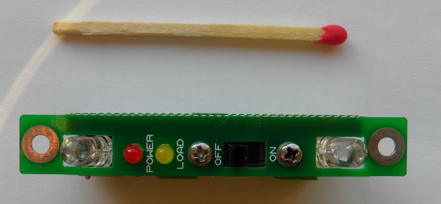
Next step is to design a proper PCB. Having cables running from the PCB to the UV and indicating LEDs isn’t that practical. So the PCB has to accommodate all components and to be easy for installing in the rocket. So the T-shape proved to be very appropriate for my purpose. And here’s how my PCB design look like in 2D, 3D and in its final version.


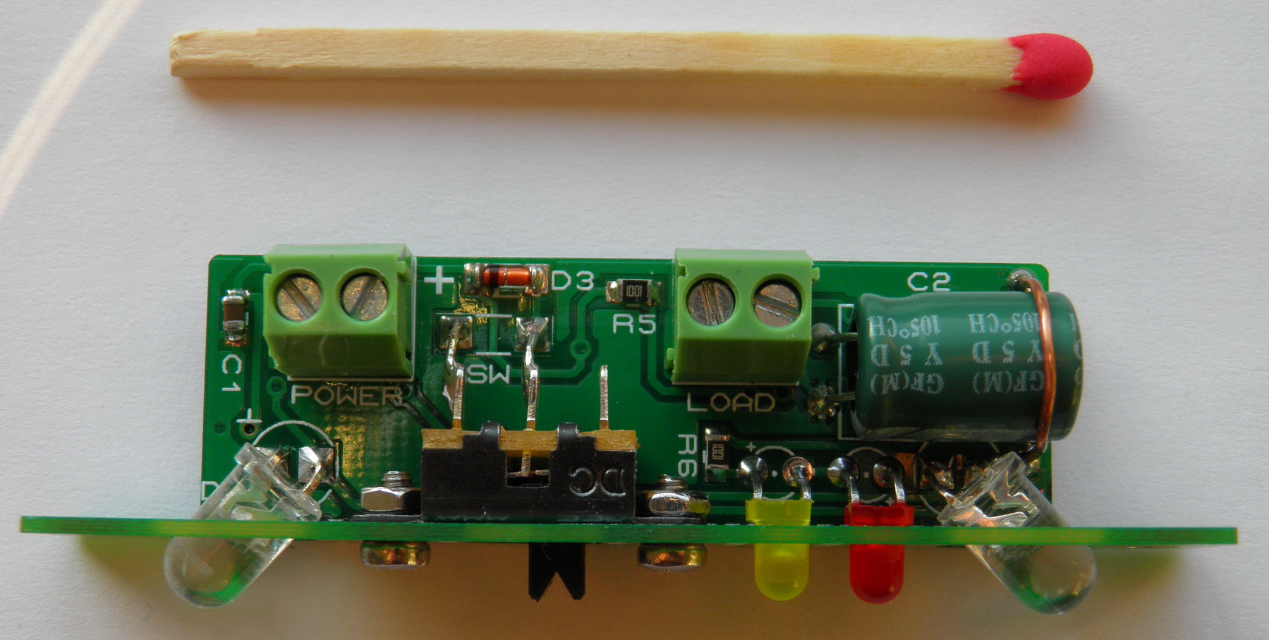
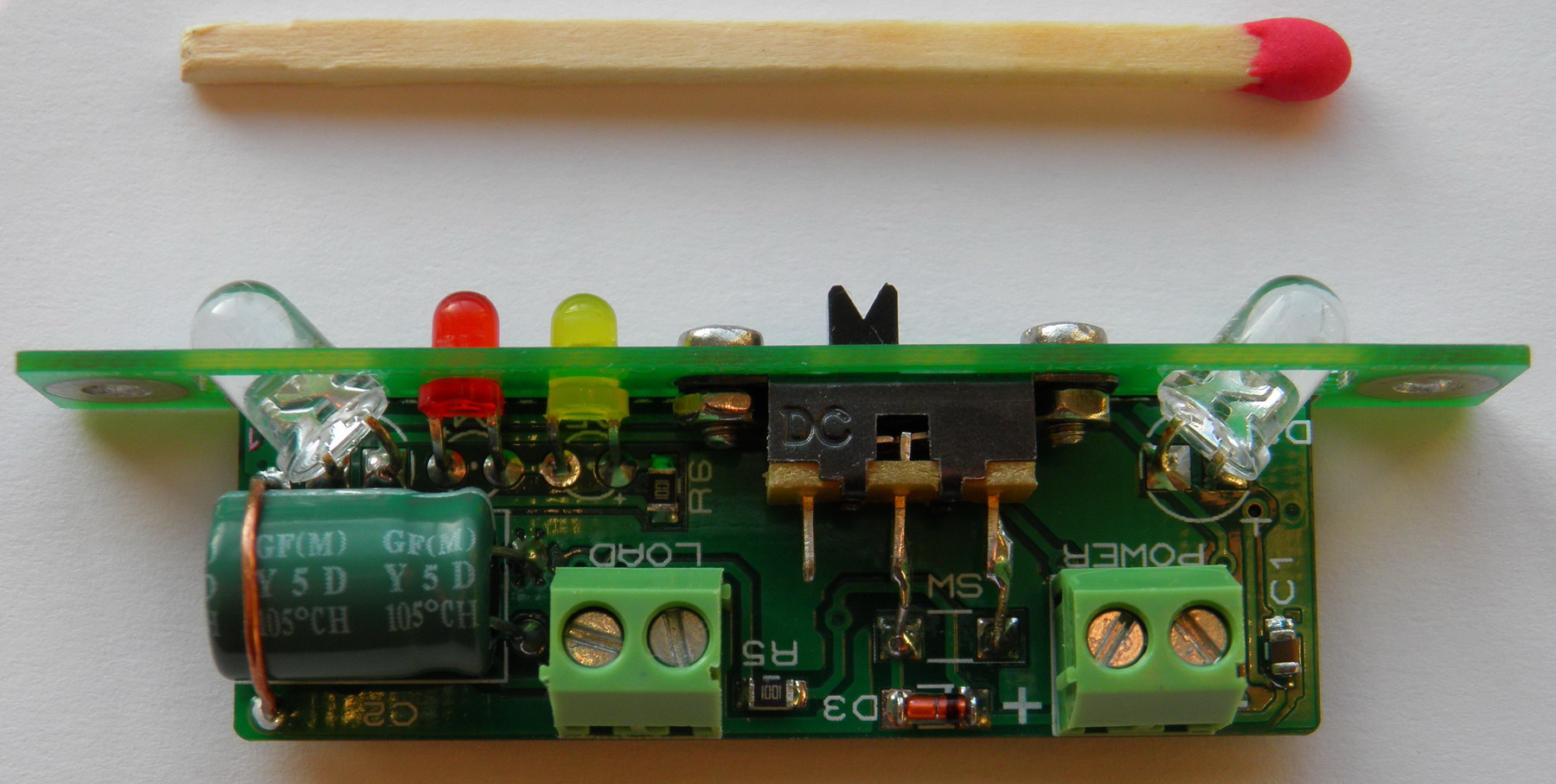
Then of course comes the PCB assembling.
For easy assembling you have to do it in a predetermined order. After breaking the two parts you solder the components except the LEDs on the main PCB. Then you have to fix the small switch on the front panel with the screws. After that you bend the LED pins and you insert them in the main PCB but you don’t solder them yet. Next step is to fix the front panel against the main PCB. Now you will see why you didn’t solder the LED pins – this step is much easier when the LEDs are still loose. Once you have inserted the LEDs in the front panel openings you solder the two parts. Then follow fixing the LEDs and connecting the switch.
Assembled, it has a front panel 65×10 mm, back panel 48×16 mm and weights 10 gr.
A short YouTube demonstration how the UV apogee detector works and test conditions.
Now the actual application:
Tthe front panel is smaller than the total height. The purpose was to minimize the front panel therefore mounting the device in the fuselage is a bit tricky. If you make an opening wide enough to insert the device straight down then the front panel won’t completely cover it. Thus you need to make the opening a little bit smaller and then incline the detector when putting it down. -VMK- made an excellent visual guide how to mount the device.


Finally some rockets made by other enthusiasts equipped with the UV Apogee Detector:
|
|
|
|
|


Some important precautions:
When you switch it on don’t lean over the upper detecting LED so it can see the sky otherwise the igniters might go on. Make sure the device is off when you connect or test it because if you touch the PCB on the back side, the OP AMP is pretty sensitive and it will pick up any minor currents flowing trough your skin, this could trigger the igniters as well.
You can find all components in the local electronic store for about $2.00. You don’t need to order a special PCB – the design has no special requirements and you can make one yourself. However there are many cheap PCB suppliers for hobbyist and if you consider ordering you will need the attached Gerber files. For small quantities (10 to 20 pcs) it will cost between $2.50 and $5.00 per piece depending on the quantity ordered and the PCB supplier you have chosen.
Your solution is very elegant and much cheaper than commercial apogee detectors. I However we don’t have any experience in electronics.Do you sell the items or do you know somebody who can make one for us?
I am working on a school project. We want to make and launch water rockets with the children. At this moment we are testing water rockets. However we don’t have a apogee detector for deploying our parachutes. The rocket some rockets didn’t survive the landing.
Hello Arthur,
I am glad you find the apogee detector useful but this is not a commercial project and I can’t sell you any detectors.