
After I made the GSM-GPS tracker, I’ve realized that the cell coverage is usually not available at sites where rockets are being launched. For a while I’ve been thinking of making an independent from the cellular network tracker for rockets, planes etc. With the LoRa SX1278 chips this became an easy task.
TRANSMITTER
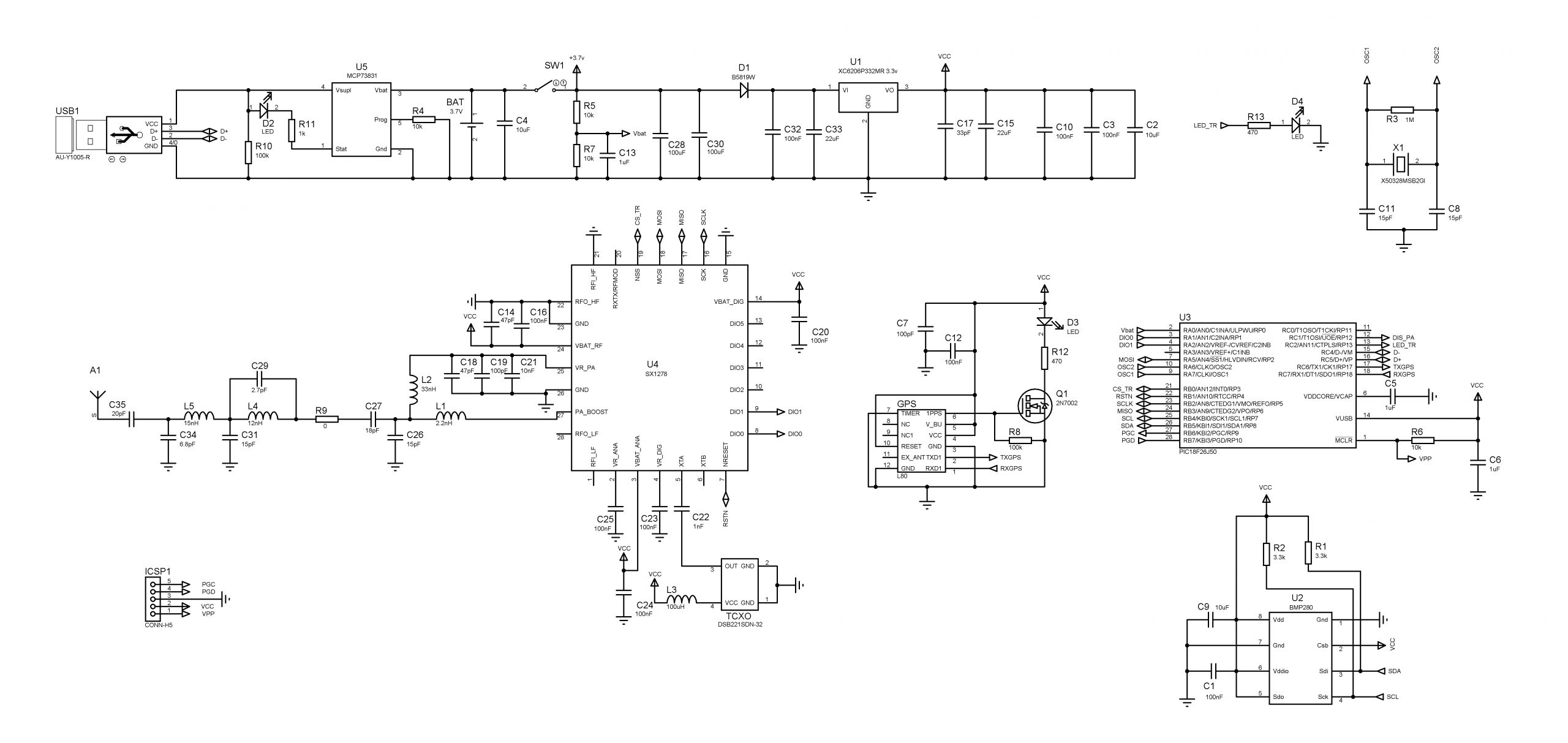
Transmitter part is straight forward following the recommended hardware design by Semtech. For better results I am using an inexpensive 32 MHz TCXO instead of a Crystal. 26 MHz clock source works too, however you will need to re-calculate the frequency register settings accordingly. Because the GPS altitude estimation is relatively inaccurate, for altitude measurement I’ve installed a barometric pressure sensor BMP280. There is also a built in LiPo charging circuit powered from the USB port.
RECEIVER
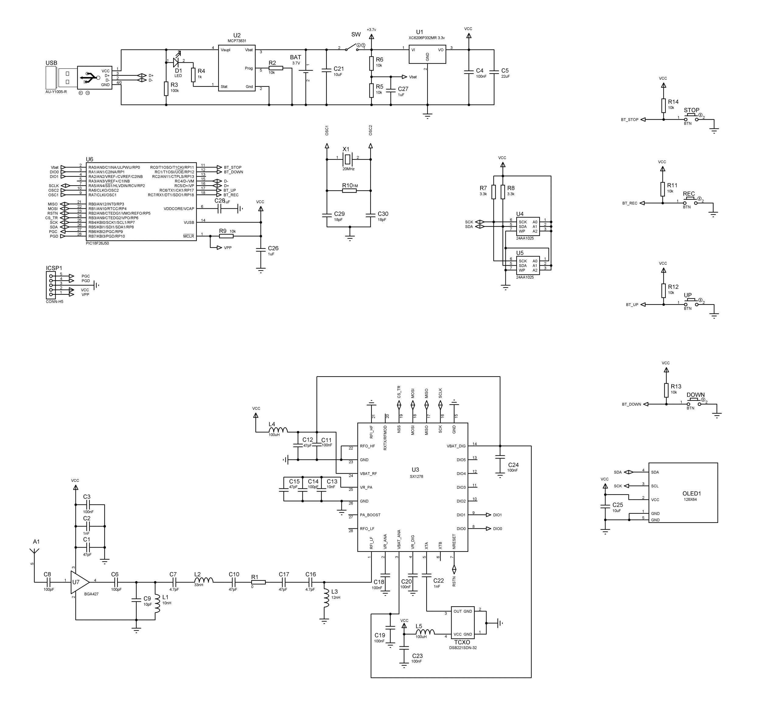
This receiver is also following the recommended hardware design by Semtech. For better results I am using an inexpensive 32 MHz TCXO (+-1ppm) instead of a Crystal. Similar to the transmitter there is also a built in LiPo charging circuit powered from the USB port. In addition to that this receiver has a128x64 OLED display, memory to record data for about an hour and some buttons for screen control. There is also a 10dB LNA (BGA427) to boost the signal and increase the link distance. Both parts TX and RX are powered by a 3.7 LiPo battery.
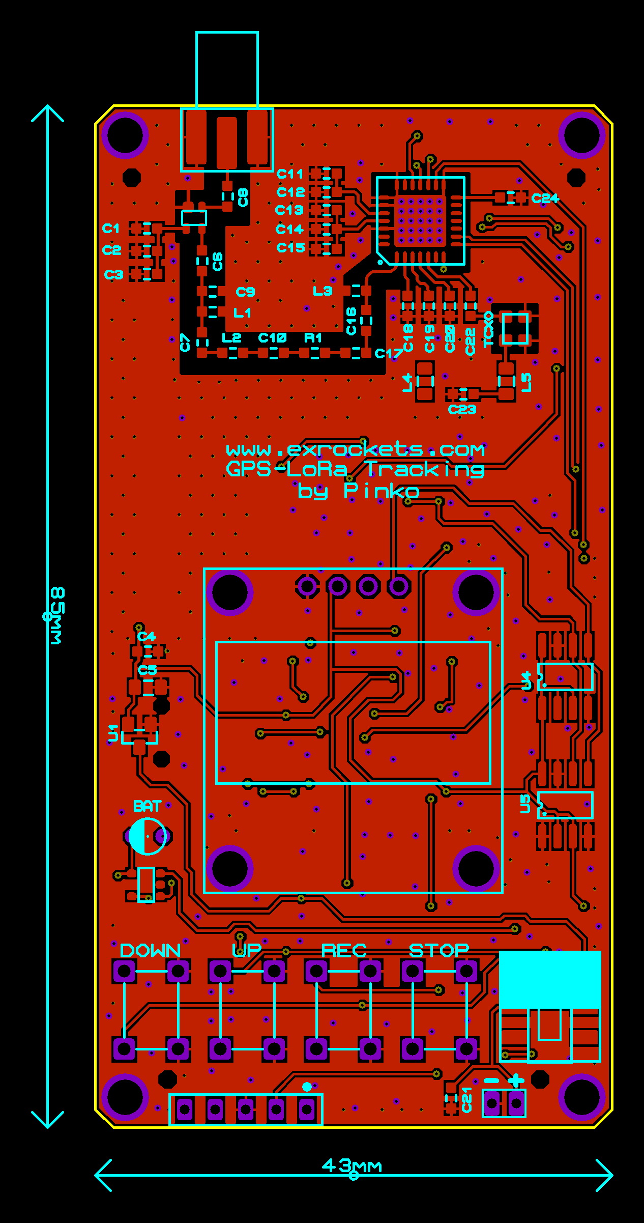
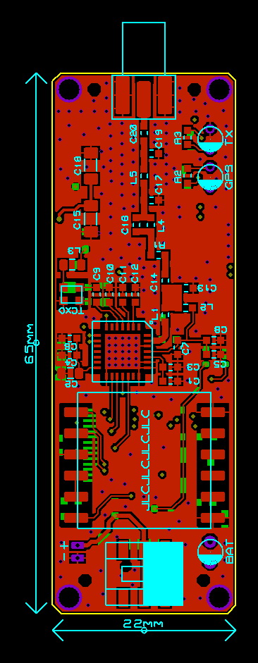
PCB DESIGN AND ACTUAL DEVICE
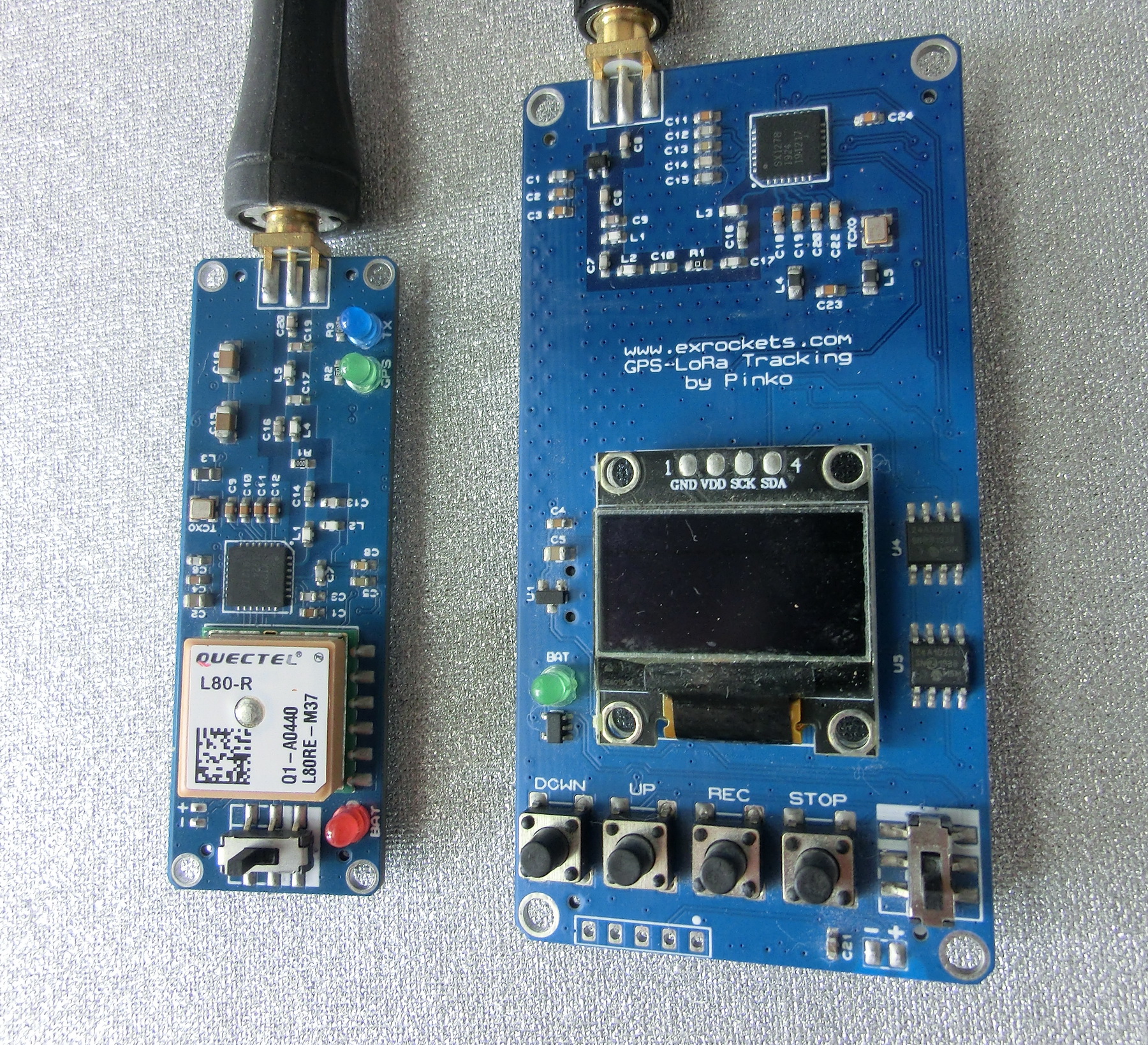
LoRa SX1278
Semtech SX1278 is a transceiver chip using LoRa modulation. You can find more information about the LoRa modulation technique here. Now I am going briefly to explain my findings when I was working with this chip.
Power – The SX1278 has a maximum output power of 100mW but you have to make sure the battery can supply about 150-160 mA peak current, otherwise the chip might reset.
Frequency – this chip support different frequency bands from 137MHz to 525MHz but I have chosen the 433MHz band since it is not licensed and it is a good compromise between antenna size and RF signal propagation.
SF – The higher the Spreading Factor, the less susceptible is the link to noise and interference and the higher is the reception range. However higher Spreading Factor also means longer transmission time.
SX1278 can support SF12 but I was unable to establish reliable link with this Spreading Factor. I’ve asked on Semtech’s boards but got no response so far. On other hand link established with SF11 proved to be very stable.
BW – Channel Bandwidth is important parameter since it affects the RF link in opposite way to the Spreading Factor. Higher Bandwidth means the link is more susceptible to noise and interference, reception range is lower and transmission time is shorter.
This transceiver can support Bandwidths from 7.8kHz to 500kHz. In my test 62.5kHz is the lower limit for Crystals and 15.6 is the lower limit for TCXO (+-1ppm) for establishing a reliable link.
EC – Error correction code – this will increase the packet size by adding additional bits for error correction but it will also increase the reception range. Of course EC 4 works best but it practically doubles the packet length.
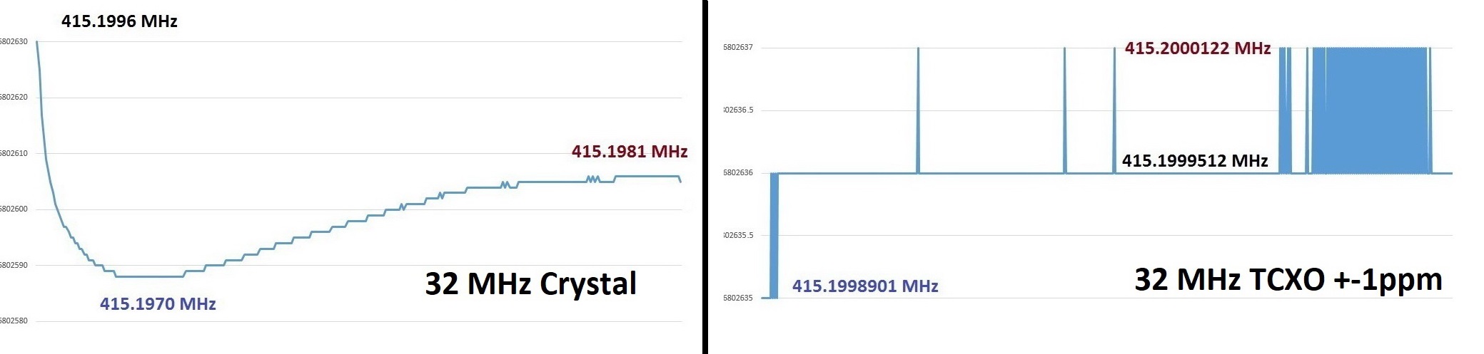
Clock source – TCXO or Crystal? According the datasheet the LoRa modulation allows for +-49% variation in the clock source from the center frequency and still the chip being able to decode the packet. Having a more stable clock of course allows for lower Bandwidths and higher Spreading Factors. I’ve done a simple test to see the temperature drift in a crystal compared to a TCXO. Here’s a chart of both running for some time and how the frequency deviates during this time.
ANTENAE
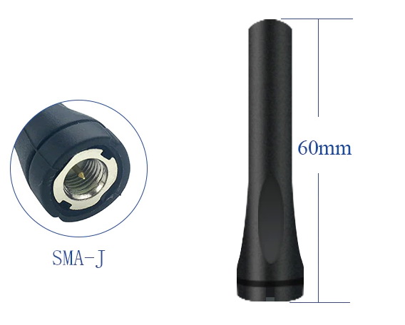
Transmitter antenna is a simple 433 MHz whip antenna from Aliexpress with +1.5 dBm gain.
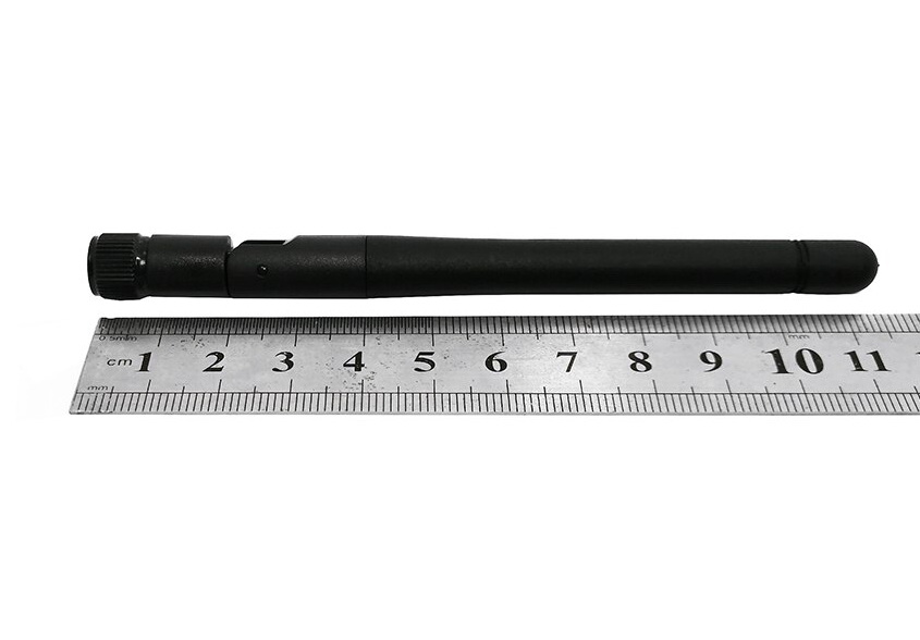
And for the receiver I tested a foldable whip antenna again from Aliexpress and a DIY 433 MHz Yagi antenna.
The Yagi antenna has 4-elements with +10 dBm signal gain and was constructed from aluminum flat ribbons. All calculations were done using VK5DJ’ Yagi Calculator including the required BALUN made from piece of coax cable.
TESTING
First thing to do before testing was to find noise free spot on the 433 MHz band with sufficient bandwidth for my tracker. You don’t actually need to do this, but for best range and performance it’s always advisable to select frequency which is not occupied by other devices. For that purpose I used an inexpensive USB SDR stick and AIRSPY SDR Studio. If you don’t have a SDR USB stick, don’t worry – I’ve built in a function in the receiver that can help you to find the free frequencies, but this will be explained later in the software part.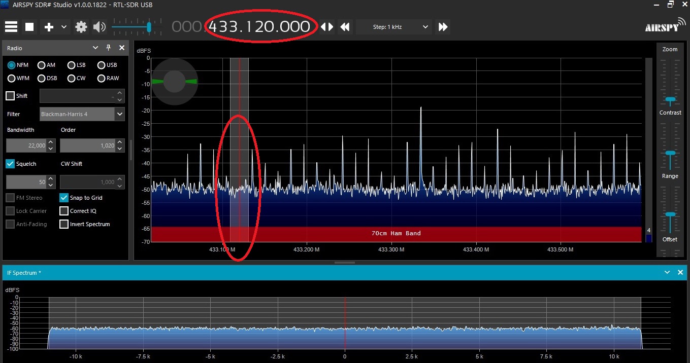 Once I determined that the 433.1200 MHz was free of other transmitters, I set up the transmitter and receiver to the same center frequency using the PC host program for the tracker kit (details for that later). Also I set the bandwidth to 20.8 kHz for both.
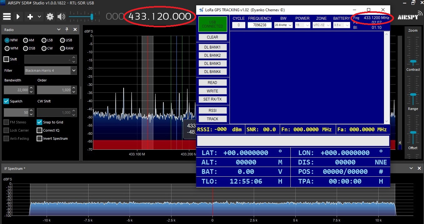 First test was to see the range within line of sight. For that I placed the transmitter on the roof at about 30m above ground and drove away for few kilometers. Checked the signal and it was strong. Then I drove further away – at about 28km distance I reached the hills where the signal disappeared using the whip antenna. Then I switched to the Yagi antenna and the signal was still strong. At about 30km I was on the top of the hills and signal reception was still strong. As soon as I went behind the hills and no longer in line of sight the signal disappeared. So the reception range in line of sight is definitely more than 30km but there is no suitable place near me for testing.
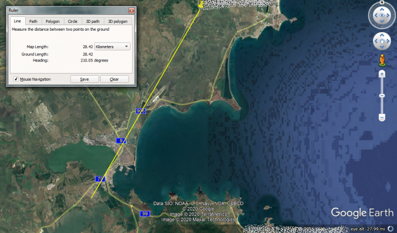 Second test was with transmitter placed on the ground hidden in the bushes:
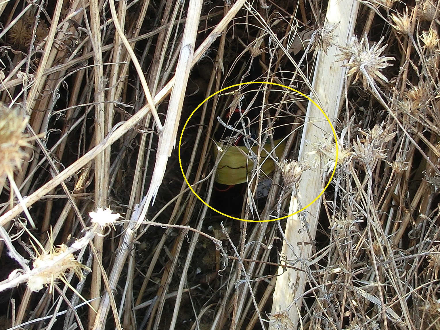 It was sunny day and I could see far away the field where I was testing the tracking kit. You can get an idea of what kind of terrain I used for the test.
 The finishing point was far back, you can barely see the hills on the background.
 Test results were far better than I would have expected. The field as you can see has some ravines and since the transmitter was on the ground the reception really depended on where I was at the moment. But simply lifting the receiver above my head was sufficient to improve the reception significantly.
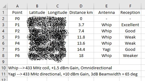 This table summarizes the reception range measurements. As you can see from the table above in point 5 at about 15km from the transmitter I had to use the Yagi antenna because I was in a ravine where I lost the signal with the whip antenna. However switching to the Yagi increased the signal strength significantly. Once I was out of the ravine I switched back to the whip antenna. At the 18th kilometer (P6) I reached the hills still receiving signal with the whip antenna. When I started climbing the hill the signal got stronger but it was no longer within the purpose of this test.
As a conclusion when the rocket/plane is in the air in line of sight, the reception range is at least 30km. Once the model rocket/plane is on the ground strongly depends on the terrain lay and vegetation with range up to 18-20 km on the open field. However in the worst case scenario tests I’ve recorded range reduction down to 5-6 km in woody hills but this rarely can be the terrain where we launch rockets and model planes. Nevertheless using a grid search of 5-10 km per grid depending on terrain will allow you to cover very large area with this tracker.
FIRMWARE
After developing an USB bootloader, I’ve made a PC firmware flashing tool which comes in handy when new firmware has to be uploaded in the devices. The Bootloader is fully protected inside the Microcontroller and can’t be re-written and/or erased. So even if the flashing process is suddenly interrupted for example by a power failure, the device can be re-flashed which makes it virtually impossible to “brick” the LoRa GPS tracking kit with firmware updates. Firmware updates became very straightforward and easy to execute by users.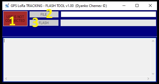 FIRMWARE UPDATE PROCEDURE:
1. Connect the device (either transmitter or receiver) to the PC with the USB cable
2. Start the GPS LoRa TRACKING – FLASH TOOL
3. Turn on the device
4. Wait until the red indicator (#1) turns green and says “USB CONNECTED”
5. Wait until the program indicates “DEVICE RECOGNISED)
6. Click on button FILE (#2) and select the firmware file (latest files are included in folder DATA FILES)
7. Wait until data is loaded (a lot of strange digits and letter will appear)
8. Click on button “FLASH” (#3) and confirm that you wish to continue
9. Wait until firmware flashing has finished
10. Restart the device by switching it off and back on
11. That’s it flashing is done
Again – don’t worry you can’t “brick” and render it inoperable –the Bootloader is protected and if something goes wrong, all you need to do is to re-flash the firmware.
The firmware and the Bootloader were written in POSITRON BASIC compiler for PIC Microcontrollers – excellent inexpensive compiler, written by Les Johnson, with lots of libraries, tools and very friendly and supportive community. Many professional and commercial products operate with firmware written in this language, definitely worth taking a look if you are interested in PIC Microcontrollers.
SOFTWARE
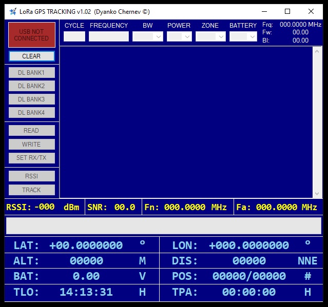 For easy set-up and improved functionality I’ve written a small PC application. Some of the buttons and functions are available for both, receiver and transmitter and some specific for each device.
First you start the application, then connect the USB cable and start the device. After 5-6 seconds the device will be recognized and the red rectangle in the top left corner will turn green, saying “USB CONNECTED”.
Note: The very first time the device is connected to a PC it might take a bit longer to install all drivers and the time allowed for USB connection will expire at which point you simply have to restart the device by switching it off and back on.
Once the device is connected and recognized, the program will display the current settings and firmware revision, as well some buttons will become available depending on whether transmitter or receiver has been plugged in.
FUNCTIONALITY
Settings:
1. CYCLE (TX) – the time in seconds between transmissions, 0 means constant transmission, it is not advisable since constant RF noise deteriorates the GPS accuracy
2. FREQUENCY (TX and RX) – a code, representing the center frequency – should be the same for TX and RX. The actual frequency is displayed in the upper right corner where it says Frq:000.0000 MHz
3. BW (TX and RX) – the channel bandwidth, should be the same for TX and RX. Higher Bandwidth means the link is more susceptible to noise and interference, reception range is lower and transmission time is shorter. Bandwidth of 20.8kHz is best suited for long range and stability
4. POWER (TX) – transmitter power – 0 means minimum power and 15 means maximum power. Higher power means longer link range but shorter battery life
5. ZONE (TX) – time zone in which the device is being used. Because the GPS only outputs the UTC time, for easy clock synchronization you can adjust the time. Does not affect the link in any way.
6. BATTERY (TX) – minimum battery voltage for transmission. If the battery falls below this voltage, the transmitter will not send packets. This is to prevent full battery discharge and potential damage
System Information:
1. Frq: – current frequency calculated from the frequency code
2. Fw: – firmware revision
3. Bl: – bootloader revision
Buttons:
1. CLEAR – will reset the form
2. DL BANKx – use this to download tracking information, recorded in the receiver’s memory
3. READ – read the device’s current settings
4. WRITE – apply the current settings to the device. The device will reboot after that
5. SET RX/TX – reserved for future use with an aerial packet repeater
6. RSSI – use this to scan the RF spectrum few MHz above and below the current center frequency. It can be used to find which frequencies are occupied and which are free and respectively set the tracking kit to the least noisy frequency
7. TRACK – although the receiver is standalone device, you can connect it to the PC/Laptop and receive the information on your screen. *Note – I was planning to add direct link with Google Earth so the tracking can be displayed directly in Google Earth
PC tracking:
1. RSSI: – packet’s signal strength. Lower values indicate lower signal strength, note the value is negative
2. SNR: – signal-to-Noise strength, higher values mean better signal quality and lower in-band noise
3. Fn: – nominal frequency. This the frequency at which the transmitter was preset
4. Fa: – actual frequency. Due to temperature variation, acceleration load, crystal aging, the actual frequency of the used crystal/TCXO changes. This value represents the relative frequency difference between the transmitter and the receiver. The closer these values he better. With higher relative difference between both TX and RX, lower channel bandwidths will become unstable
5. LAT: – GPS latitude
6. LON: – GPS longitude
7. ALT: – this is relative barometric altitude above start. Since the vertical positioning with GPS is very inaccurate, I am using barometric sensor to determine the relative vertical position with respect the altitude where the TX was switched on
8. DIS: – Distance and heading to the current position as seen from the starting point. At each new packet the receiver calculates the distance and the heading to the current position as seen from the starting point based on the GPS coordinates. Note this is only with respect to the initial starting point, so if you move around with the receiver, the distance won’t account for your movement and still the distance and the heading will be with respect the initial starting point
9. BAT: – transmitter’s battery voltage
10. POS: – each packet sent from the transmitter has an embedded serial number which is compared to the total number of received packets by the receiver. Left number represents the number of received packets, and the right is the packet’s serial number. Comparing both numbers you can see if and how many packets have been dropped
11. TLO: – local time based on the PC clock
12. TPA: – packet time stamp. Each received packet has an embedded time stamp based on the GPS clock
Assuming that all settings have already been done via the PC software and the Transmitter and the Receiver have been set-up with the same center frequency and bandwidth, it is time to put the LoRa GPS tracking kit in use.
TRANSMITTER GUID
– after the TX is switched on, it will remain silent for about 5 seconds while loading internal information
– then for about 6 seconds the status LED will start blinking very fast indicating that the TX is waiting to connect to the USB
– when the TX sees no USB connection, it switches to normal operation
– Immediately after that the TX sends one packet with all zeroes, except the battery voltage, to confirm that it is alive
– next the TX stays silent regardless of the transmission cycle time set through the PC software until the GPS finds valid signal fix and the GPS LED starts blinking with 1s period
– after the GPS fix has been found, the TX waits for about 20 valid position fixes to roll from the GPS
– after 20 valid fixes, the TX averages several GPS position coordinates and sends the second packet, which now holds all coordinates. Coordinates from this packet are used from no on as the starting point for calculating the distance and the heading for each new packet
– from now the TX continue transmitting packets with the preset period even if for some reason no signal is available for the GPS so you can track it using Fox hunting techniques (later more explanation for that)
Note: if the battery voltage drops below the predetermined level, the transmitter will stop sending packets to prevent further battery discharge.
RECEIVER GUIDE
After the TX is switched on, it will remain silent for about 5 seconds while loading internal information. Next screen shows receiver’s battery voltage – wait to continue 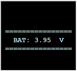 Next screen is a welcome screen showing system information – wait to continue
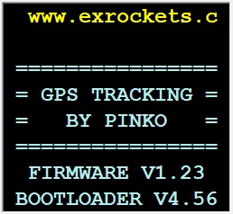 Next screen will check if the USB cable is connected – wait to continue
 USB connection has not been detected – wait to continue
 This screen explains buttons meaning. DOWN/UP means either decrease/increase or move down and up. REC means either set or continue, STOP is usually resetting the current process. Press REC (Next) to continue
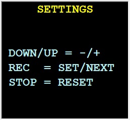 Next screen asks for the frequency mode, for now only NORMAL is available, the rest is reserved for future use. Press DOWN to select NORMAL mode
 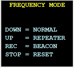 Next screen displays the current frequency set in the memory. You can adjust it by pressing DOWN/UP. If no changes are required or the frequency has been set, press REC to set and continue. Pressing STOP will reset the device. Any changes made here remain only for the duration of this session, the preset frequency in the memory is not being changed
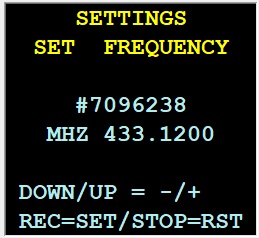 Next screen displays the current bandwidth set in the memory. You can adjust it by pressing DOWN/UP. If no changes are required or the bandwidth has been set, press REC to set and continue. Pressing STOP will reset the device. Any changes made here remain only for the duration of this session, the preset bandwidth in the memory is not being changed
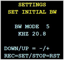 Next few screens will display the currently selected frequency and bandwidth for few seconds – wait to continue
Then we arrive at the main menu. Press DOWN to go in RECEIVER mode, UP to erase memory, REC to view memory, STOP for fox hunt.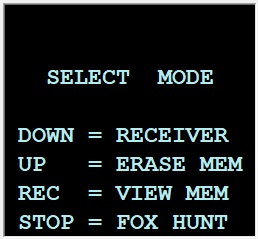 RECEIVER (TRACKING MODE):
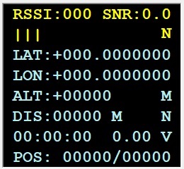
This is the main working mode where data is being received from the transmitter and visualized on the screen. The meaning of the fields is the same as in the PC application. 1. RSSI: – packet’s signal strength. Lower values indicate lower signal strength, note the value is negative
2. SNR: – signal-to-Noise strength, higher values mean better signal quality and lower in-band noise
3. N: – indicates that currently tracking data is not being recorded in the memory
4. LAT: – GPS latitude
5. LON: – GPS longitude
6. ALT: – this is relative barometric altitude above start. Since the vertical positioning with GPS is very inaccurate, I am using barometric sensor to determine the relative vertical position with respect the altitude where the TX was switched on
7. DIS: – Distance and heading to the current position as seen from the starting point. At each new packet the receiver calculates the distance and the heading to the current position as seen from the starting point based on the GPS coordinates. Note this is only with respect to the initial starting point, so if you move around with the receiver, the distance won’t account for your movement and still the distance and the heading will be with respect the initial starting point
8. 00:00:00: – packet time stamp. Each received packet has an embedded time stamp based on the GPS clock
9. 0.00 V: – transmitter’s battery voltage
10. POS: – each packet sent from the transmitter has an embedded serial number which is compared to the total number of received packets by the receiver. Left number represents the number of received packets, and the right is the packet’s serial number. Comparing both numbers you can see if and how many packets have been dropped
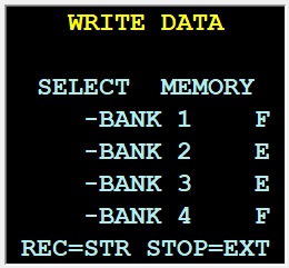 During tracking mode you can start recording the received packets in the memory. For this press REC button and it will show the following screen:
Using the UP and DOWN button select a memory bank where you want data to be recorded. F/E – F means the bank has some data written in it or E is for 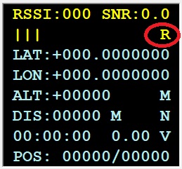 empty, thus there is no data in the selected memory bank. Once you have selected a memory bank, you can start recording data by pressing REC button, or if you press the STOP button you can stop recording the tracking data (if it was currently recording). Pressing any of the both buttons REC or STOP will return you to the previous screen with the tracking data. If data is being recorded in the memory, instead of N in the upper right corner a R will appear.
ERASE MEM:
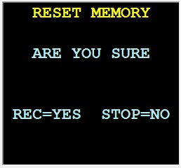 This menu allows you to format all memory banks.
Just follow the instructions – you will be asked to confirm few times that you are sure, buttons for confirmation change on each screen where you are asked to confirm. This is done in order to prevent accidental deletion. Pressing any other button than the confirmation button will restart the device.
When you have browsed through all confirmation screens, an erasure counter will appear. Once the memory erasure has finished the devise will reboot.
VIEW MEM:
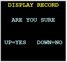 This menu will visualize the currently recorded data in the memory banks.
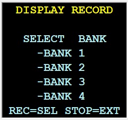 If you press UP for yes, the next screen will appear. DOWN for no will restart the device and bring you back to the beginning.
Use the UP and DOWN buttons to select which data bank should be displayed. Once you have selected the desired memory bank, press REC to display the data or STOP to exit and reboot the device.
 Displaying the memory will bring forward the same screen as in tracking mode.
Use the UP and DOWN buttons to browse through the different packets. If you wish to return to the main screen, press STOP to restart the device.
FOX HUNT:
This mode is used whenever the GPS is unable to output valid position fix and the transmitter is sending 0-filled packets or if the transmitter is close enough and outputting positional data but the accuracy is low and we will use the signal strength of each packet to find the transmitter. More on Radio Fox Hunting
For this purpose best is if you are using a directional (Yagi) antenna but an omnidirectional whip antenna can be used too with good results. The main idea is that you hold the receiver close to your body and use the body as RF signal shield. Then you start slowly turning around and see in which direction the signal is strongest. Then you move forward in this direction and check again.
At some point the signal will be too strong and you won’t be able to differentiate where the signal is coming from because the receiver is working in maxim sensitivity. In this case we need to dampen the signal to a level where we can distinguish the signal level in the different directions. Since we can’t control the transmitter’s strength, we have to lower the signal strength in the receiver. This can be done by lowering the receiver’s sensitivity using one of the options available in Fox Hunt mode.
Then with lower receiver’s sensitivity we continue looking for the transmitter utilizing these techniques until we visually or audibly identify the transmitter’s position.
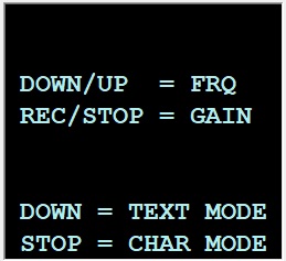
While in TEXT mode or in CHAR (chart) mode you can change the frequency by pressing DOWN and UP or the receiver’s gain (changing sensitivity) by pressing REC or STOP. But first select which mode for fox hunt you want to use – press DOWN for TEXT mode or STOP for CHART mode:
TEXT MODE:
In text mode the signal strength is displayed with numbers and signal indicator.
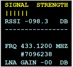 1. RSSI: – packet’s signal strength. Lower values indicate lower signal strength, note the value is negative
2. FRQ: – current center frequency, it can be changed by pressing DOWN and UP
3. #: – a code, representing the center frequency
4. LNA GAIN – receiver’s gain (amplification) – Lower values mean less amplification, thus lower receiver’s sensitivity. Note that the value is negative. The gain can be changed by pressing REC or STOP
CHART MODE:
In CHART mode, the signal strength is displayed as a graphic. In this mode is displayed not only the center frequency but also several hundred kHz above and below the center frequency. This mode has slower response time and it’s more suitable for overall channel occupation assessment than actual Fox Hunt.
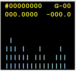 1. #: – a code, representing the center frequency
2. G: – LNA GAIN – receiver’s gain (amplification) – Lower values mean less amplification, thus lower receiver’s sensitivity. Note that the value is negative. The gain can be changed by pressing REC or STOP
3. current center frequency, it can be changed by pressing DOWN and UP
4. packet’s signal strength. Lower values indicate lower signal strength, note the value is negative
PC SOFTWARE AND FIRMWARE DOWNLOAD:
LoRa_GPS_Tracking_Main_App.zip – User Program
LoRa_GPS_Tracking_Bootloader_App.zip – Firmware FLASH program
USB_Bootloader_FIRMWARE.zip – Bootloader Firmware for PIC18F26J50
TX_1_06_26MHZ.zip – Transmitter firmware for latest 26MHZ TCXO version
RX_2_08_26MHZ.zip – Receiver firmware for latest 26MHZ TCXO version
RX_2_09_26MHZ.zip – Receiver firmware for latest 26MHZ TCXO version
Leave a Reply